The definition of where an assembly stops being considered a toy and where an assembly begins being considered a serious robotic project can not be made accurately.
In fact, any toy that can move around and perform a series of previously scheduled tasks (either by the user or the manufacturer, already in the project) can be considered a result of robotics.
So most of the toys that now use electronic resources and that are common in our stores, by their behavior and technology, can perfectly fit into robotics, of course in its early stages.
What we propose in this article is an initiation to robotics, in the form of a project that at the same time works as a curiosity, also leads the assembler to acquire experiences mainly in the treatment of mechanical parts.
Our Robot has a brain, a mechanical part and a sensorial part, which means that within the principles of robotics, in its most advanced form, it fits as a perfectly situated member on a reasonable scale.
Of course, all these parts are minimal, but enough so that it has its own very interesting behavior.
Thus: the sensor is formed by two phototransistors which act as electronic "eyes", interacting the robot with the environment.
It "sees" light and dark regions, distinguishing them.
The brain is the simplest type which can exist: just one bit of capacity, similar to an amoeba - if we can make such a comparison that commands the mechanical system from the information coming from the sensors.
However, even with just one bit its behavior is not properly digital, but rather analogical, with a scale of stimulatory and response levels which gives it a very interesting behavior.
Much more than a logical unit, we can associate this "mini brain" with a bionic unit. (We let more advanced readers evolve the project in the direction of a "positronic" unit with the proper permission from Dr. Asimov).
Finally we have the mechanical part, which simply gives it motion, and which is made up of two motors that take our robot to anywhere, as long as it is on flat ground.
The result of coupling all these features is quite interesting:
We have a robot whose movement depends on the light and its origin. Light stimuli cause the robot to search for light regions.
Objects and obstacles "are perceived" by the robot which circumvents or changes direction with its approximation.
For the assembly, we were careful to rely on materials that could easily be obtained in our market and even improvised from scrap.
Imaginative readers will have no difficulty in modifying the mechanical part according to the availability of material.
How it works
The principle is very simple as can be seen from the diagram in Figure 1.
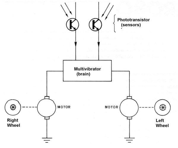
Astable multivibrator feeds two common motors.
In the control of the driving time of each branch of the astable it is connected the sensors, two phototransistors.
With equal degree of illumination, the astable has time periods of driving by equal branches, and with that the motors rotate in the same speed.
Under these conditions the robot advances in a straight line.
If one of the phototransistors is illuminated more than the other, the astable becomes unbalanced, and one of the motors turns faster and the other one slows down.
The result is that the robot tends to curve.
If there is no light source that balances the conduction of the phototransistors, the robot will make a full turn until it finds a region of equal illumination that brings the circuit to equilibrium.
If a light source is found on this turn, the balance is struck and it moves straight in the direction of that source.
Balance adjustments in trimpots take the robot to the desired behavior.
Two LEDs attached to the multivibrator transistor collectors also give the robot an interesting visual effect.
These LEDs flash in accordance to the light it sees, in a sort of luminous response to the external stimulus.
The circuit is supplied with 6 V from 4 medium batteries, and the motors are from toys for this voltage, with low current consumption.
Assembly
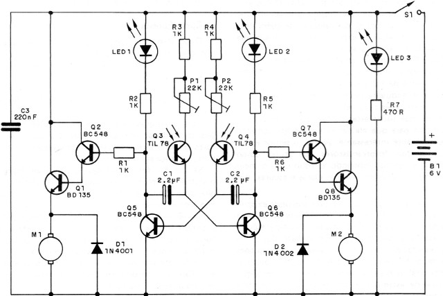
In Figure 2 we give the complete diagram of the electronic part of the robot.
In Figure 3 we have a suggestion of a printed circuit board.
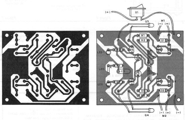
In addition to the normal care with the components we have some recommendations to make.
The transistors are all common, and the power transistors (BD135) can be replaced by equivalents.
These transistors are chosen according to the current of the motors.
We opted for 6 V motors of small current. If the motor current is high, heat radiators may be needed in the transistors and, of course, the battery life will be compromised.
The resistors are all 1/8 or ¼ W and the electrolytic capacitors must have a working voltage of at least 6 V.
The readers who want can experiment with changing the values of the capacitors to modify the behavior of the robot.
LEDs are commonly red and phototransistors are of the TIL78 type. Equivalents can be tried.
Note that these phototransistors must be built in such a way to determine the visual field of the robot.
In the mechanical part we give the details of its location.
The diodes in parallel with the motors avoid the action of the high voltage generated by the switching which can affect the transistors.
For adjustment, there are two trimpots whose values ??can be between 22 and 47 k.
The electronic part can be tested even before the mechanical part is ready.
To do so, simply connect S1 and place the batteries in the holder. With phototransistors in the dark, the motors work alternately at lower frequency shifts.
With the illumination of the two, the speed of the exchange and the blinking becomes greater.
By darkening one phototransistor and illuminating the other, one of the motors must rotate faster than the other.
After checking the operation of the electronic part it is just needed to think about the mechanical part.
Assembly of the mechanical part
In the head, there is the printed circuit board, besides the LEDs.
In the body, there is the power supply formed by 4 average batteries, in an appropriate holder.
In the feet, it is fixed the two motors, one for the movement of each wheel and another for the phototransistors.
In Figure 4, we give details of the coupling of the engine to the driving wheels.
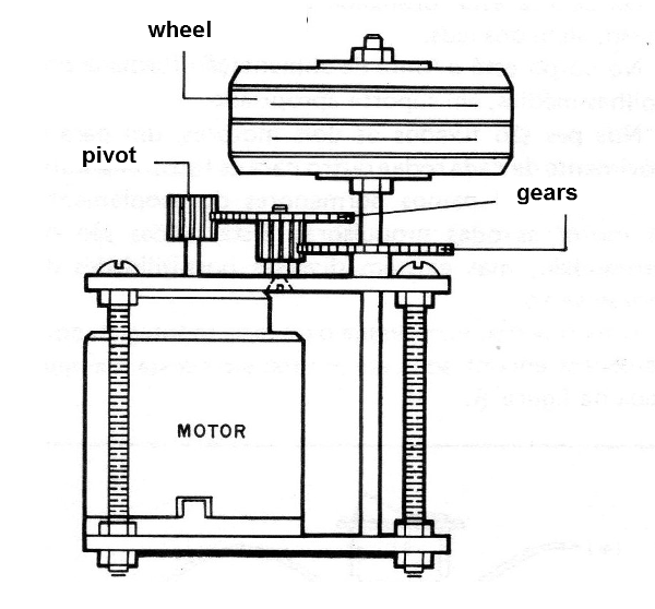
These wheels are from aeromodels, but there are several possibilities for improvisation.
An economic suggestion for an assembly, with elements found even in scrap, is the one shown in Figure 5.
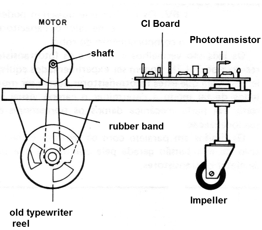
For this we use three wheels, two propellers, connected to the engines.
The third one is mobile and works only to give balance to the whole set.
These propulsion wheels are improvised with typewriter reels.
You can easily get these reels from tapes in offices or with anyone who has a machine.
Test and Use
The final test is made taking into account the lighting of the sensors.
For it to go straight, the trimpots should be adjusted in the absence of light.
Cover the phototransistors to make this adjustment or point them to a single source of light.
To use, simply connect the robot in place that has a light source located as a lamp or even a candle.
Observe obstacles and see how it behaves.
Q1, Q3 - BDI35 or equivalent - NPN transistors
Q2, Q5, Q6, Q7 - BC548 or equivalent NPN transistors
Q3, Q4 - TIL78 or equivalent - phototransistors
LED1, LED2, LED3 - Common red or other colored LEDs
D1, D2 - 1N4001 or equivalent - silicon diodes
M1, M2 - 6 V motor
PI, P2 - 22 k - trimpots
S1 - Single switch
B1 - 6 V - 4 D or C batteries
R1, R2, R3, R4, R5, R6 - 1k x 1/8 W - resistors (brown, black, red)
R7 - 470 ohm x 1/8 W - resistor (yellow, violet, brown)
C1, C2 - 2.2 uF - electrolytic capacitors
C3 - 220 nF (224) - ceramic capacitor
Miscellaneous: a printed circuit board, holder of 4 medium alkaline batteries, wires, welding, gears, wheels, material to manufacture a robot etc.


