Theory
The simplest way to add motion to robots, mechatronic devices, and other automation equipment is to use a dc motor. They are cheap, small, efficient, and can be found in a wide range of sizes, shapes, and power ratings.
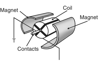
A conventional dc motor is formed by an arrangement of coils and magnets that creates motion for electric power. Figure 1 shows the typical construction of a small dc motor.

We can use these motors to move any mechanism directly or, by adding gears or tracks, to reduce speed or increase power. The basic dc motor properties that must be considered when using them in robotics or mechatronics projects are as discussed below.
Direction
When powered from a dc power supply (battery or other source), the direction of the shaft rotation depends on the direction of the current flowing through the motor. by reversing the current, we can reverse the direction of movement of any device drive by a dc motor.
Speed
The speed of a dc motor, expressed in rotations per minute (rpm), depends on the current and the load. We must consider two situations when using a dc motor. In the first case, the motor operates without a load (or with a constant load). The speed will increase to a maximum that depends on the applied voltage.
In the second case, the motor operates with a variable load (i.e., the motor must power some kind of mechanism with forces that depend on the moment or the task).
In this case, the speed depends on the load: higher required power = lower speed.
Characteristics
When looking for a dc motor for a particular application, the designer must determine its characteristics. The following are important considerations.
Voltage
Small dc motors can be obtained with voltage ratings in a range from 1.5 to 48 V.
The specified voltage indicates the nominal voltage, which is the applied voltage that makes it run normally (i.e., producing maximum power and consuming nominal current). In practice, the nominal voltage is important, because it indicates the maximum recommended voltage that can be applied to the motor.
Current
The current flow through a motor, when powered with the nominal voltage, depends on the load. The current increases with an increase in load. It is important to avoid letting a motor run with excessive loads that can stall it. In the stalled condition, the motor becomes a short circuit for the current, and all applied power is converted into heat. The motor can quickly burn up in this condition. Common dc motors have operating currents in the range of 50 mA to more than 2 A.
Power
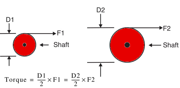
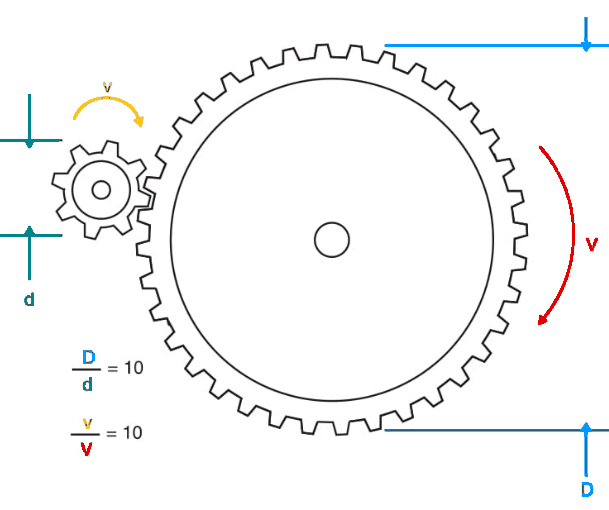
The power is given by the product of voltage × current. In projects involving robots and mechatronics, it is normal to rate the amount of force that a motor can generate in terms of its torque (twisting power). As shown by Figure 2, the torque is the force released by the shaft, and it depends not only on the motor’s electrical and mechanical characteristics but also on the shaft diameter. This specification is important, as the force that a mechanism powered from a dc motor can provide depends not only on the motor itself but also on the mechanism coupled to it. Therefore, if gearboxes are added, as shown in Figure 3, the speed can be decreased, and the power will be increased by the same factor.


For instance, if a gearbox employs a reduction gear that is ten times the diameter of the motor drive gear, the speed is reduced ten times, but the power is also increased by a factor of ten.
In robotics and mechatronics, the use of gearboxes of all sizes and reduction ratios are commonly used to match the characteristics of a selected motor to a desired task. Therefore, when using a motor, is important to know the torque rating because, starting from that figure and knowing the reduction rate of the mechanism to be moved, we can easily find the final power that can be generated by a system.
Speed
It is normal to specify the speed of a dc motor in open or no-load conditions. The speed can be in the range of 500 and 10,000 rpm according the type, size, and other characteristics of a common dc motor. Remember that this speed will be reduced by a considerable factor when the motor is operating under loaded conditions.
Suggestions for Projects
The simplest way to add directional control for a robot is using two motors. If the two motors are on, the robot goes in a straight line. If one motor is on and the other off, the robot turns in the direction of the motor that is off. The same type of control can be provided if the motors runs at different speeds.
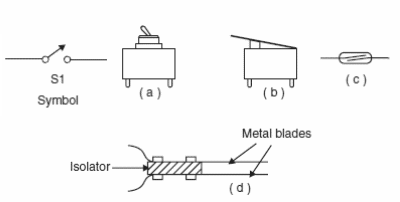
Simple mechanical systems such as shown by Figure 4 can also be assembled with a single dc motor coupled to a gearbox. The up and down movement and speed can be controlled directly by the motor.

Starting from these concepts, some projects can be suggested:
Draw a control circuit for a small robot that can walk in all directions, using single switches for this task.
Design an experimental elevator controlled by switches.
Design a crane using small DC motors and gearboxes.


