The diode conducts only half of the semi cycles of the ac power line voltage. The capacitor filters (smooths out) the voltage pulses, keeping the voltage level applied in the motor as constant as possible. The value of the capacitor depends on the current drained by the motor in these applications. A simple rule for motors powered from 3 to 15 V is adopt 1,000 ?F of capacitance for each ampere of current. For instance, use a 470 ?F (500 ?F) for a 500 mA motor. Using this circuit, you can powered your application from such ac supplies as small transformers.
Full-Wave Control
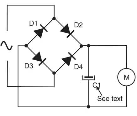
The circuit shown in Block 6 uses only half of the semi cycles of the ac voltage. If you don’t intend to use the other semi cycles in another part of the circuit (to control another motor for instance), it would be better use the configuration shown in Figure 2.

The filter capacitor is chosen in the same manner as described in the half wave control. This circuit can also be used in dc circuits to keep the direction of a motor independent of the polarity of the voltage source, as shown in Figure 1.
In this figure, we show a circuit in which a single switch is used to reverse the dc power supply, reversing the direction of motor M1 but not M2. M2 is wired to the same line, but it runs only in one direction, thanks to the design of this block.


