Relays are not the only components that can be used to control a load with an electric signal. The transistor is also applicable to this function, and there are many advantages do doing so. They are ideal for many applications in robotics and mechatronics.
The principal advantages are as follows:
Low cost
Small size
High speed
High sensitivity
There are two basic types of transistors: bipolar and field-effect. Let’s see how they can be used as switches.
Bipolar Transistors
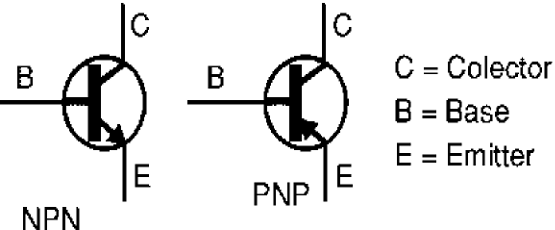
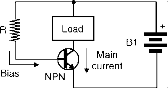
There are two types of bipolar transistors, categorized according the internal structure of the semiconductor material from which they are manufactured, as shown in Figure 1. The basic difference between the two types is the direction of the current flow while they are functioning. As shown in Figure 3.13, the NPN transistor conducts a large current between collector and emitter when the base is made positive with respect to the emitter.
In a typical transistor, the current between collector and emitter can be 100 times higher than the current applied to the base, meaning that this devices can produce gains of 100 or more. In the operation of an NPN transistor, the collector must be connected to the positive pole, and the emitter to the negative pole, of the voltage source. See figure 2.
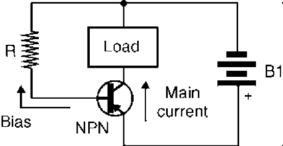
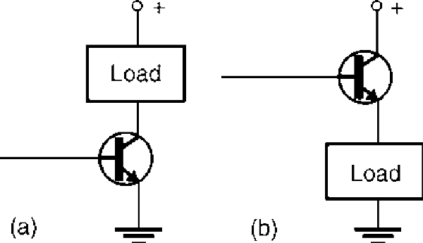
On the other hand, the PNP transistor conduces a large current between the emitter and collector (the reverse direction as compared with an NPN transistor) when the base is made negative with respect to the emitter, as shown by the Figure 3. The voltage source must have the positive side connected to the emitter and the negative to the collector. The load to be controlled by a transistor can be installed between the collector and the power supply or between the emitter and power supply as shown by figure 4.
The main characteristics to be considered in a bipolar transistor, when using it in a project design, are the following:
Vce. This is the maximum voltage that can be applied between collector and emitter without burning up the transistor. Typical values are between 20 and 500 V.
Ic. This is the maximum current that can flow through the collector terminal; it is the maximum current that can be controlled by the transistor. Typical values are between 100 mA and 10 A. Transistors that can control currents above 500 mA are termed power transistors and normally must be mounted on heat sinks.
Pd. This refers to maximum power dissipation, i.e., the maximum amount of power that can be converted to heat by the transistor. Transistors with a Pd of 1 W or more are also classified as power transistors and must be mounted on heatsinks.
In robotics and mechatronics circuits, a bipolar transistor can be used to perform many tasks. One is just turning a load on and off by applying a small current to the base. The load can be a relay, motor, lamp, or any other electronic circuit, as we will see in the following blocks.
Field Effect Transistor or FETs
Field effect transistors are produced in four basic types, as shown by Figure 5 In 5a, we see the junction FET (J-FET), and in 5b, we represent the two types of metal-oxide semiconductor field effect transistors (MOSFETs).
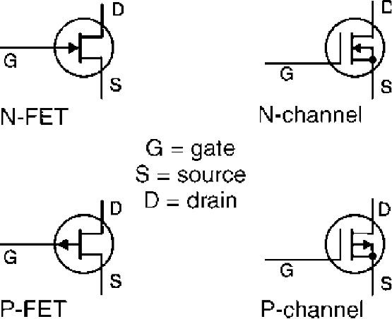
The operating principle of these transistors is the same: the current between drain and source can be controlled by a voltage applied to the gate. The direction of the current and the polarity of the voltage applied to the gate (G) depends on the type.
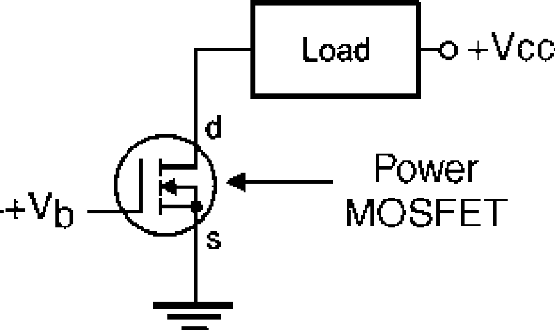
The N-channel conducts the current when the gate is made positive with respect to the source. Figure 6 shows an application in which the load is installed between the power supply and the drain (d) of the transistor. FETs can be used for the same functions as bipolar transistors, as we will see in the blocks presented in this section.
The main characteristics to be observed in FETs are the following:
Vds. This is the maximum voltage that can be applied between the drain and source. Typical values are in the range between 50 and 1000 V.
Id. This is the maximum current across the device. Values between 50 mA and 100 A are common. Special transistors, referred to as power FETs or power-MOSFETs, can control currents above 1 A. These are power transistors that must be mounted on heat sinks.
Pd. This is the maximum amount of power that the transistor can convert to heat when operating.


