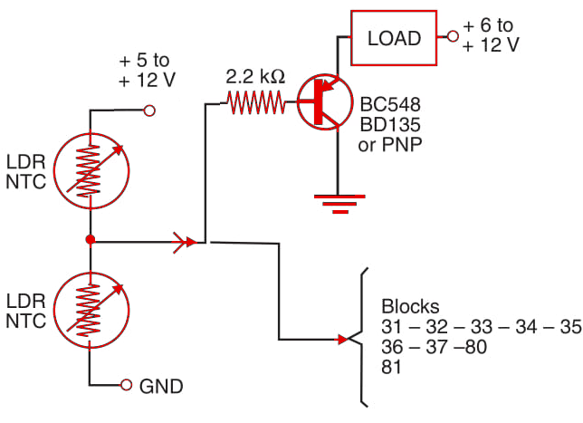
In the LDR version, the output signal of this circuit depends on the amount of light falling on the sensors. If the amount of light simultaneously rises or falls on the two sensors, the circuit state does not change. But if the amount of light rises in LDR1 as compared to LDR2, the circuit triggers on. The potentiometer is used to adjust the trigger point of the load.

An application in robotics projects is in the “follow-the-line” robot. The same concept can be used with other sensors. Note that the circuit action is nonlinear, as one of the sensors exerts more influence on the circuit than the other. The designer must take into account the operating range of the circuit when used in a project.


