Obs. This article was originally published in Portuguese in a Brazilian magazine and then translated into English to be part of my book Mechatronics for the Evil Genius (TAB- 2006)
This kind of project uses both mechanical and electronic parts and has a special visual effect. You can use the elevator as a toy to decorate a miniature building or in science fairs.
The basic project described here has a minimum of resources, meaning that the reader with a good imagination can add other resources or even intelligence by controlling it with a computer. Many options will be given.
The elevator is not powerful because it uses a small DC motor powered by a DC power supply or even common cells. However, depending on the gear-box or the torque system, it can be used to lift weights up to 100 grams.
This project is used as part of the mechatronic course for high school students at Colegio Mater Amabilis in Brazil. The pupils have to put their imagination to work to create the best elevator using gear- boxes and reduction systems made with simple parts such as diskettes, rubber bands, CD boxes, and other common items (Figure 1).
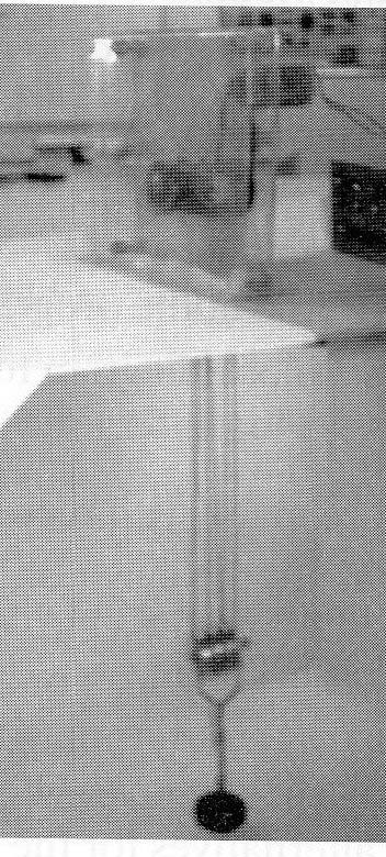
It is important to note that by using the same principles applied in this project other automatic devices such as miniature mobile bridges and industrial machines, doors, and windows can be created.
Objectives
Build a simple elevator using common parts.
Add an automatic system to make the elevator stop at different floors.
Learn how gearboxes work.
Work with formulas to calculate differential pulleys.
Organize a competition to see who can build the most powerful elevator.
How It Works
The project of the mechatronic elevator can be divided into two parts: (1) the electronic circuit, which is used to control the motor, and (2) the mechanical part, which includes the gearbox or reduction system and the differential pulley.
Electronic Circuit
To allow the best control of the motor, including the speed, the solution adopted uses a pulse width control (PWC).
The pulse width modulation (PWM) control is coupled to a directional control to allow the motor to move the elevator up and down. The directional control and an intelligent block are added to avoid having the elevator push against the top and bottom of the course and to stop at the programmed floors. Figure 2 shows a block diagram for the electronic circuit.
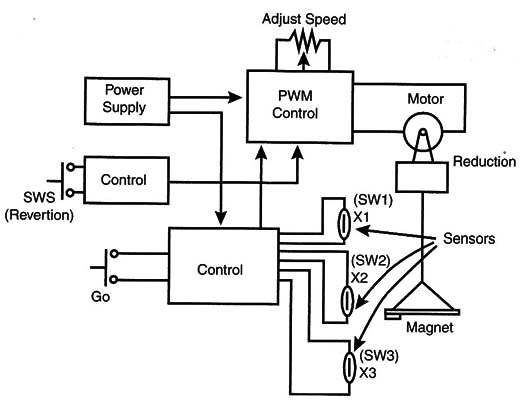
The sensors are made with reed switches. Attaching a small magnet to the elevator, it will close the reed switches when moving up and down at each floor, as shown in Figure 3.
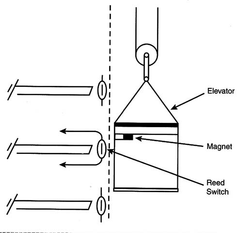
The circuit uses a 6-Volt DC motor. Therefore, the reader has two alternatives for the power supply. The first is the one shown in Figure 4 that can deliver up to 1 A to a 6-volt circuit, The second option is to use C or D cells.
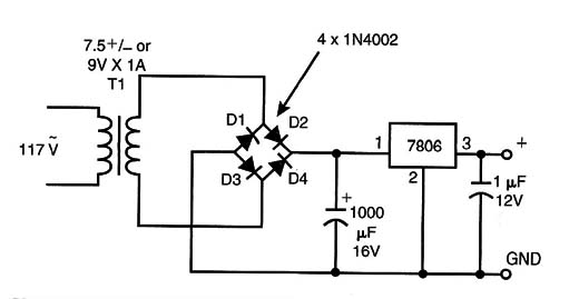
The transformer used in this version has a primary coil rated for 117 VAC, or in accordance with the AC power line, and a secondary coil rated to 7.5 or 9 volts with currents up to 1 amp. The integrated circuit (IC) must be mounted on a heatsink, and the C1 capacitor must be rated to 16 volts or more.
The K1 relay is used to stop the elevator at each floor (or level) as determined by the sensors SW1 to SW3. The sensors are reed switches activated by a small magnet attached to the elevator.
Each time the elevator stops, the operator must wait a moment and then press SW4 to start the circuit again and allow the elevator to go on its way.
At the end of the course of the elevator (that is, at the highest and lowest points for the elevator), the reader must add sensors to invert the direction of the motor. But for the simplest project this task can be performed by a switch, as shown in Figure 2.
Magnets, end-of-course switches, H-bridges, and mechanical sensors are other solutions for this task.
The trimmer potentiometer allows the reader to adjust the speed for the best operation of the system according to the power of the motor and the characteristics of the mechanical system.
Mechanical Part
The reader can adopt many mechanical solutions to build this elevator. Common materials such as wood, plastic, or even metal can be used to make the structure of the building that holds the elevator.
For the elevator, two solutions should be considered for transferring the power from the motor to the cabin. One is shown in Figure 5 and uses a reduction box made with wheels and rubber bands. The wheels were made from diskettes and attached to a CD box. It is a very simple solution adopted by many students who build this elevator.

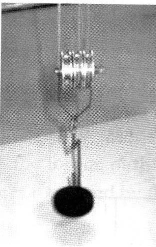
Additional power for increasing and reducing the speed can be achieved using a differential pulley made with plastic or metal and cotton wire. Figure 6 shows how a differential pulley can be made.
How to Build
Figure 7 shows the schematics for the electronic circuit adopted in the elevator’s project.
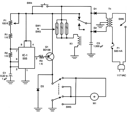
The recommended motor is a 6-volt DC motor, rated to enough power to move the elevator. For small motors, such as the ones that can be driven by AA cells, the elevator can handle objects weighing a maximum of 50 grams.
Of course, this depends also on the maximum speed and the reduction ratio given by the mechanical parts. By using these small motors, the power can also be delivered by four C or D cells.
The sensors are small reed switches placed in the structure of the building and activated by a small magnet glued to the elevator. It is important to ensure that the elevator does not escape from its trajectory (or elevator shaft) while it is moving, which would change the alignment and disallow the magnet from passing directly in front of the sensors.
A system of rails can be used to avoid this alignment problem. The circuit can be mounted on a solderless board or printed circuit board (PCB), according to the resources of the reader.
Testing and Using
First test the electronic control for the motor away from the mechanical system. Adjust P1 and see if the motor will run gently at all speeds. If you have any problems controlling the speed, change the value of C1. Depending on the motor, lower values can cause problems at high speeds, and higher values can make the motor vibrate at low speeds. To activate the motor run in this test, it is enough to place the magnet near any sensor (SW1 to SW3) or press SW4.
Once you have verified that the motor runs well, attach it to the elevator and test the mechanical system that triggers the sensors to see if the motor has enough power to move the cabin.
Adjust P1 to the ideal speed. Do not allow the elevator to run too fast. Be sure the rubber bands are correctly adjusted to the wheels in the reduction system so they will not slide when rotating.
Once tested, you can use your elevator in demonstrations or science fairs, or you can upgrade it with the suggestions givel after the Parts List.
Elevator with Power Supply Included
CI-1 – 555 IC
Q1 – BC136 – PNP transistor
D1, D2, D3 – 1N4002 – silicon diodes
R1, R2, R3 – 1 k ohm x 1/8 W – resistors (Brown, Black, red)
P1 – 100 k ohm – potentiometer
C1 – 0.22 µF to 1 µF – ceramic or polyester capacitor
C2 – 470 µF x 12 V – electrolytic capacitor
C3 – 1,000 µF x 12 V – electrolytic capacitor
T1 – Transformer: primary 117 Vac or according the power supply line and secindaty coil at 6 volt xc 500 mA or according the motor
K1 – 6 V x 50 mA relay
SW1, SW2, SW3 – NO reed switches
SW4 – Push button NO
SW5 – DPDT switch (see text)
SW6 – SPST on/off switch
M1 – 6-Volt DC motor (see text)
F1 – 500 mA fuse and holed
PCB or solderless board, wires, plastic box for the control, mechanical parts for the building and elevator, small magnet, solder, etc.
Using a Gearbox
Gearboxes are very efficient methods for increasing the power and adding speed reduction to DC motors.
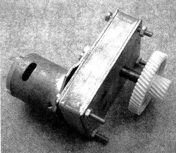
Many types of gearboxes can be found in model stores or in toys. The reader can use a gearbox in the elevator, replacing the mechanical system that was made with rubber bands. Figure8 shows a common gearbox that can be used in the elevator.
When using a gearbox, the reader must attempt the reduction ratio given by the mechanical system.
The reduction ratio is the factor by which the speed is reduced and the power increased. For instance, a 1:100 gearbox raises the torque of the motor by a factor of 100 and reduces the speed by the same amount.
Gearboxes with reduction factors between 50 and 100 are recommended for this elevator. Gear motors or gearboxes including DC motors can also be used.
Adding Other Automatic Routines
Besides automatically stopping at each floor and reversing the motor at the end of course, many other automatic routines can be added to the mechatronic elevator.
The reader who is experienced in electronics can design many small circuits or blocks to make the elevator operate in different ways. The following is a short list of suggestions for additions to your elevator:
Turn on a light in the building when the elevator stops at a particular floor.
Add call buttons that make the elevator go to the floor where the button was pressed.
Add a microcontroller programmed to make the elevator accomplish predetermined tasks.
Add sensors to detect when an object is not perfectly aligned in the elevator.
Design a digital indicator to show the floor where the elevator is resting or passing.
Controlling the Elevator by Using a Computer
Figure 9 shows a simple interface that can be used to control the elevator with the help of a computer.
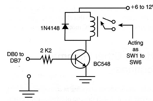
An additional circuit that could be added might be a data acquisition interface plugged into the same port. This data circuit will allow the circuit to send information to the computer about the position of the sensors. A program can be created to control the elevator automatically by using signals sent by the sensor.
Another circuit to control the motor can use stepper motors as described in other articles in this site. This type of motor can be used with many advantages in applications where precision and fine movements are needed. Another advantage of using a stepper motor is that it is easier to control with a computer.
Cross Themes
Pulleys, differential pulleys, gears, and the work it takes to move an object are all studied in physics. Thus, the elevator project can teach students a great deal about those subjects if used as a crossover project in high-school-level curriculum.
Calculating Pulleys and Gearboxes
Pulleys and gearboxes can be calculated by using the formulas shown in Figure 10.
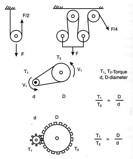
As the reader can see, the torque and speed are altered according to the ratio of the diameter (or the number of teeth) of the pulleys or gearbox.
Calculating Differential Pulleys
Differential pulleys are calculated according to the formula shown in Figure 1.
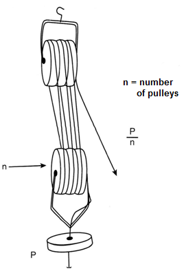
Other mechanical machines that present some mechanical advantage can be studied based on the same principles used in the elevator.
The Elevator Challenge
Who can build the best elevator? A competition can be designed to determine the elevator with the best performance. Rules should be determined regarding the specifics of the elevator. The elevator that can lift the most weight or the one with the greatest number of added functions could be the winner.
More Circuits and Ideas
Many circuits or functional blocks can be added to create a fantastic elevator. A few configurations using common parts are suggested in the next section.
a) Using a Linear control
The reader can replace the PWM control with the electronic potentiometer described in this section. This circuit is not as good as the PWM control because the torque and speed can change according to the power applied to the motor. The torque and speed in this circuit can also change with the weight to be lifted in the elevator, so adjusting the circuit requires more care.
b) Adding a timer
Figure 12 shows a simple timer that can be used to stop the elevator at each floor at a particular time.
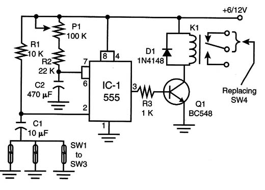
When the input (pin 2) of the 555 timer is put to the ground level by any sensor, the output goes to the high logic level and the relay turns on, cutting the power for the motor.
The output remains high and the relay remains on during a specific time interval adjusted by P1. This time depends also on C1 and can be changed according to the needs of the project.
Timer
IC1 555 - timer
Q1 - BC548 general-purpose negative-positive-negative (NPN) transistor
D1 - 1N4l48 general-purpose diode
P1 - 100 k ohm - trimmer potentiometer
R1 - 10 k ohm x 1/8 - watt resistor (brown, black, orange)
R2 - 22 k ohm X 1/8 - watt resistor (red, red, orange)
R3 - 1 k ohm X 1/8-watt resistor (brown, black, red)
C1 - 10 µF x 12 - Volt electrolytic capacitor
C2 - 470 µF X 12-Volt electrolytic capacitor
K1 - 6-Volt X 50 mA DPDT relay
PCB or solderless board, wires, solder, etc.


