The Darlington transistor can be replaced by a power metal-oxide semiconductor field-effect transistor (MOSFET) as shown in Figure 1.
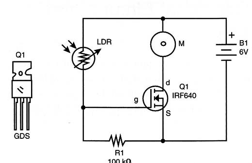
You only have to reduce the resistor to 100 k ohm..
Any common Power MOSFET rated to 2 amps or more (IRF720, IRF640, etc.) is suitable for the task.
In some cases the power supply voltage can be altered to 9 V and the motor replaced by one that can operate with this voltage.
Circuit Using a Power MOSFET
Q1 - IRF640, IRF720, or equivalent Power MOSFET
LDR - Common light-dependent resistor
M - DC motor of 6 volts or up to 500 mA
R1 - 100 k ohm X 1/8-watt resistor (brown, black, yellow)
B1 - 6 volts of power (4 AA cells and holder)
Timed Circuit
Another interesting alternative for a race uses the circuit shown in Figure .2.
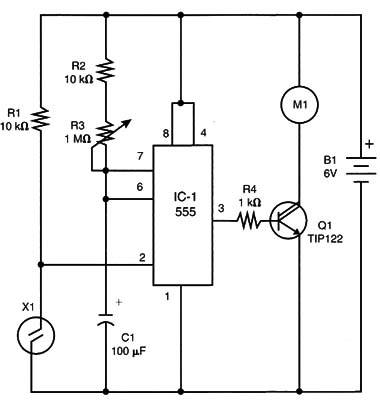
This circuit has a 555 IC configured as a timer.
When the sensor (a reed switch) is triggered by a small magnet, the circuit turns on and the motor is powered by a time interval determined by C1 and the adjustment of P1.
When triggered, the race car will run for a certain time interval. P1 can be adjusted in order to make this interval long enough to cover the distance mandated by the competition. In a race, each competitor will use a small magnet to start their cars.
Timed Circuit
IC-l - 555 IC timer
Q1 - TIP122 or equivalent, NPN Darlington transistor
X1 - Reed switch
R1, R2 - 10 k ohm X 1/8-watt resistor (brown, black, orange)
R3 - 1 M ohm trimmer potentiometer
R4 - 1 k ohm X 1/8-watt resistor (brown, black, red)
C1 – 100 µF x 12-volt or 16-Volt electrolitic capacitor
B1 - 6 volts of power (4 AA cells and holder)
Running on Rails
One problem observed in this race car is that the direction of movements depends on the precision of wheel alignment. In a race, cars will typically run in different directions, sometimes causing crashes or circular paths.
An interesting option to a race, one better used with gear-constructed race cars, is to make the cars run on rails as shown in Figure 3.
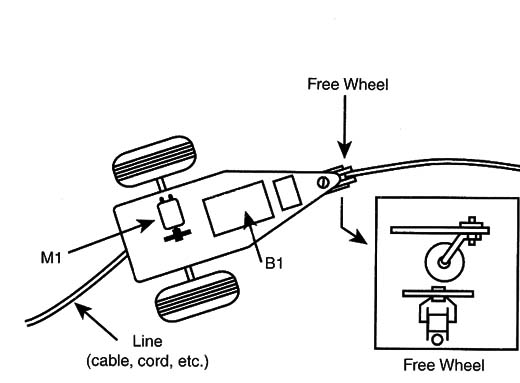
Small, free wheels run over a cable used as a rail.
Circuit Using a SCR
The circuit shown in figure 4 uses a SCR to control the motor.
In this version, a single pulse of light falling onto the SCR is enough to trigger the circuit on.
In this condition the motor remains on until the power supply of the circuit is cut.
In other words: the light pulse is only used to start the engine.
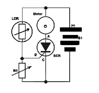
Version using SCR
SCR – 2N5064 – SCR
LDR – Common LDR
R1 – 220 k ohm to 330 k ohm x ¼ W – resistor
M1 – 6 to 9 V motor
B1 – 4 AA cells
Terminal strip, cell holer, wires, etc.
The Technology Today
Today, fan-propelled vehicles are used in swamps, but the same principle can be observed in airplanes and helicopters.
The transmission of power by gears is found in many vehicles and home appliances.
The power of your car’s engine is transmitted by gears to the wheels, moving it at different speeds. The speed is determined by the ratio of the gears’ teeth in the gearboxes.
Many home appliances that use electric motors use plastic or metal gears to induce move ment in mobile parts. Your electric mixer is one example.
Ideas to Explore
To get better performance or to learn more about th project, do the following:
Try to use gears that reduce the speed of the fan and increase the power. Many gearbox can by found in the Internet to be used in this project.
Use a tube to direct the air of the fan as a turbine. Computer fans can be used as propelers if you replace the power supply by 8 AA cells (12 V).
Change the gears by increasing or reducingthe diameter, noting which combination results in more power or more speed.
