Pulse width modulation (PWM) motor controls are very efficient for controlling the speed and torque of small DC motors. Adding a precise control to a DC motor, the reader can develop many interesting projects involving remotely controlled movement.
The basic version of the project described here can be used to control small 3- to 12-volt DC motors, draining currents up to 500 mA. Some improvements in the basic project can extend both the range of currents and the voltage of the motors.
The main objective of this project is to give the reader the resources to control small motors in mechatronics devices. The following is a short list of suggested projects that can use a PWM control like the one described here:
Automatic elevator
Automatic window
Speaking head
Fan
Model car
Of course, using his or her imagination, the reader can put the PWM control described here to work in many other projects.
How it Works
There are two ways to control small DC motors. The simplest way is to control the power applied to a load by using a rheostat wired in series with the motor as show figure 1.
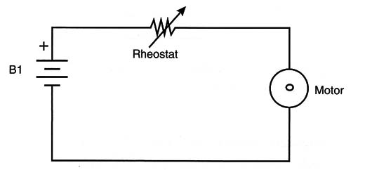
This configuration is called a linear control.
Together the rheostat and the load form a variable voltage divider. By changing the resistance of the rheostat, dhe voltage applied to the motor also changes and consequently so does its speed and torque.
The main inconvenience in this type of control is that the current pulled, or used, by the motor passes across the rheostat. Therefore, the greater the amount of current pulled by the motor, the greater the amount of heat generated in the rheostat.
Another problem to consider is that, because the motor represents a variable load, the circuit involved in controlling the DC motor can be unstable, mainly at low speeds.
It is very difficult to make the motor start softly while keeping the torque constant along the range of operation.
Motors are variable loads because they change their electrical characteristics as the speed and torque changes. In a practical linear control, the rheostat is not used to directly control the current across the motor, but the current through the base of a transistor, as shown in Figure 2.
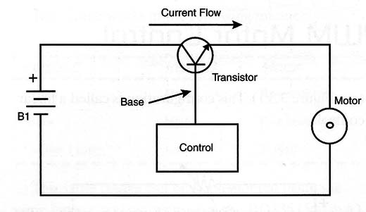
So the rheostat dissipates less heat as the transistor is used to control the main current in the circuit, and therefore the transistor dissipates more heat. In other articles in this site we will give details of how to construct a linear power control, also known as an electronic rheostat.
The second way to construct a linear power control is by using the PWM control. Because this is a much more efficient way to control the amount of power applied to a load, it is also used in other applications’ power supplies, such as common appliances like computers, TVs, VCRs, and so on.
A PWM control is also called a switched mode power supply (SMPS).
The basic idea of a PWM starts from the use of square voltage pulses that power a motor (see Figure 3).
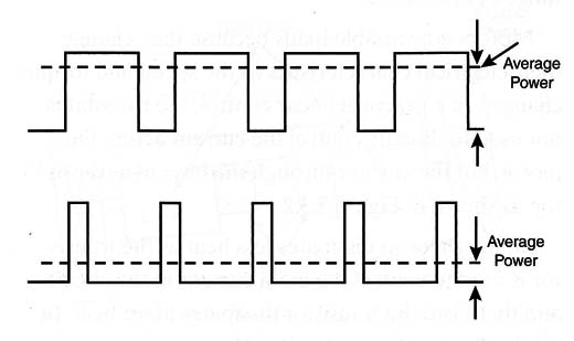
The amount of power applied to the motor depends on the duration of each pulse, or the duty cycle, of the control voltage. If the duration of the pulse is the same as the interval between the pulses, we say that the duty cycle is 50 percent, and the average power applied to the load is 50 percent.
If the duration of the pulses is extended, the average power applied to the motor increases by the same proportion. Figure 3.(beloww) shows what happens in this scenario.
It is easy to see that controlling the width of the pulses can change the average power applied to a motor or to any other load. The process used to control the width of the pulses that are applied to the load is called modulation, and this kind of circuit is termed pulse width modulation (PWM) power control.
With this in mind, we can move on to a practical PWM control. A basic configuration for a practical PWM is given in Figure 4.
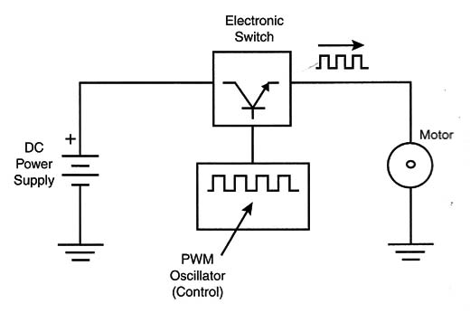
A bipolar transistor (or other transistor) is wired to a variable-duty-cycle oscillator. When the oscillator is running, the transistor turns on and off at the frequency of the oscillations, applying a square wave to the motor.
Note that, when the transistor is on, the resistance between the emitter and the collector can be considered to be zero and no power is generated across it. (The power is the product of the voltage drop and the current; because the voltage is practically zero, the result is zero power.) When the transistor is off, no current flows through it and the power dissipated is zero, too.
In the real world, the transistor can’t pass from the on state to the off state, or vice versa, quickly enough to avoid the generation of heat. The transistor needs a finite time for the change of state. It is important to note the heat generated by the switching process in this kind of circuit. However, it is generally very low as compared to the heat generated by linear controls.
Another advantage of PWM controls happens when controlling DC motors. DC motors controlled by PWM can maintain more constant torque over the entire speed range.
The Basic Project
A PWM control for small DC motors can be implemented in a variety of ways using common parts. Our basic project uses a common 555 integrated circuit (IC) in a stable version, driving a positive-negative-positive (PNP), medium-power transistor, as shown by the blocks in Figure 5.
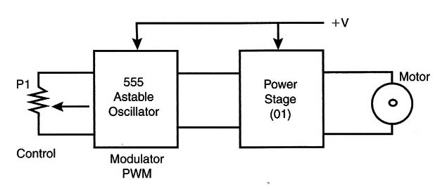
This circuit is not a real PWM but a quasi-PWM.
Using fewer components, we can build a simple configuration that functions on a basic level and is enough for our purposes. At the end of the project, we will give other versions for the reader who wants to do more with this kind of circuit.
This circuit is formed by a 555 timer IC operating in a stable configuration. The circuit generates a square wave, with the frequency changing by the change of the duration of the pulses, as shown in Fig-6.
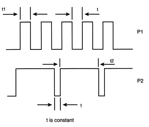
The result is that although the average frequency changes (which doesn´t happen in a real PWM control), the pulse width changes, too. This is why we say it is a quasi-PWM control.
Therefore, it is possible to control the speed and torque of the motor in a range from almost 0 percent to 90 percent of the maximum.
The central frequency is determined by the Cl capacitor. The builder must choose a capacitor that matches the characteristics of the motor. Low-value capacitors can produce very high frequencies, and the motor won,t react to the signals.
The efficiency of the circuit will fall in this case, and even the motor cannot start.
On the other hand, capacitors with very low values can cause the motor to vibrate or run with small jumps at low speeds.
The reader must experiment to find the best capacitor in the range of values suggested in the text, matching the characteristics of the motor being used.
The circuit can operate from power supplies ranging from 5 to 12 volts, and the motor ca'n pull a current up to 500 mA. Later in the chapter, in the section on upgrades, we suggest circuits that can drive more powerful motors.
Building the Control
Figure 7 shows the schematic diagram for the PWM control using the 555 IC.
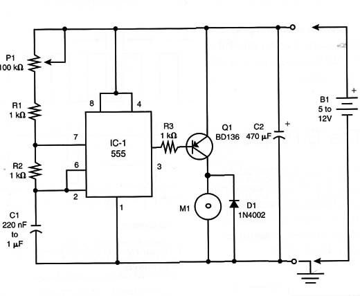
The reader can mount the circuit in a small printed circuit board (PCB) with the pattern suggested in Figure 8.
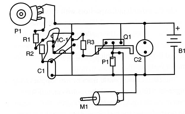
Of course, the reader is also free to make his or her prototype using protoboards or universal PCBs.
The transistor must be mounted on & heatsink, and the potentiometer can be
Wired to the circuit using long wires. If. the motor must be placed far from the control unit, it is better to mount the circuit near the motor and not near the potentiometer.
Test and Use
Connect the control to a DC motor and to a power supply. The power supply can be formed by using four AA cells or one D cell (for a total of 6 volts).
Reacting to the potentiometer, the speed of the motor will change. Notice that at very low speeds, the motor will continue to run slowly, but with good torque.
If the motor tends to vibrate at low speeds, or not to reach the maximum speed, change the value of the C1 capacitor until you find the best value for the desired performance.
PWM Control
IC1 - 555 IC timer
Q1 - BD136 or equivalent (BD138, TIP32, TIP42, etc.) medium-power PNP transistor
D1 - 1N4002 silicon diode
R1, R2, R3 - 1 k ohm - resistor (brown, black, red)
P1 - 100 ohm linear potentiometer (rotary or slide)
C1 - 220 nF to 1 µF polyester or electrolytic
C2 - 470 µF x 16 working voltage in direct current (WVDC) electrolytic
B1 - 5- to 12-volt power supply
M1 - DC motor, 5 to 12 volts, up to 500 mA
PCB, heatsink for Q1, wires, solder, etc.
Projects
Many interesting projects can be built using this control. You can even add this control to motors in other projects described in this section of the site, such as the RobCom.
Simple Elevator
Figure 9 shows how to mount an experimental elevator using this circuit. S1 is a switch that changes the direction of the motor.
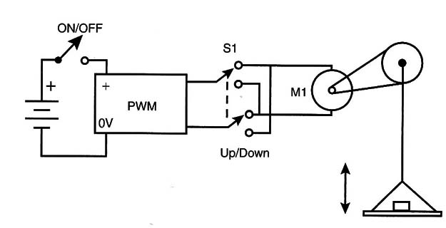
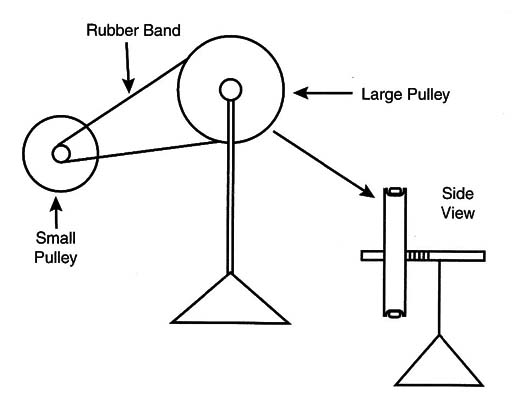
The gearbox can be found in toys, electronic appliances, or other mechatronic devices. You can also reduce the speed and increase the torque of the system by using a reduction system made with rubber bands as shows fiture10.
Automatic Window
Figure 11 shows how you can use a small DC motor with a gearbox and PWM control to make an automatic open and close system for your window.
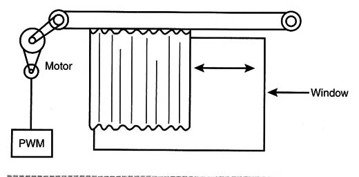
It is important to prevent bumps at one end of the course or the other (when the window is totally open or closed) so no hitches occur when using switches to open the circuit.
Fan
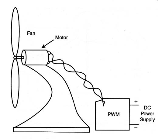
Figure 12 shows how a small electric table fan can be built using a PWM control. The speed can be controlled across a large range of values, according to the amount of breeze you want.
Increasing the Power Figure 3 shows how a Darlington transistor can be used to control high-power motors.
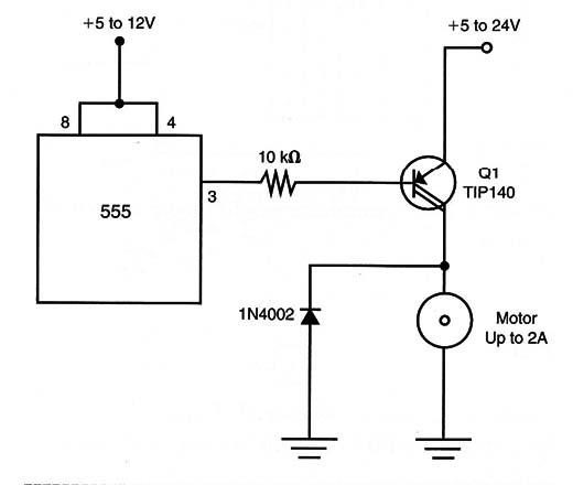
A TIP122 can be used to power motors up to 2 amps. The transistor must be mounted on a heatsink. Other transistors such as the TIP140 can be used to control motors up to 4 amps.
A Power MOSFET can be used in the circuit without causing any visible change. Remember that Power MOSFETs need 9 volts or more for them to have good control of a load.
A Practical PWM
The circuit shown in Figure 14 uses two diodes in an arrangement that changes at the same time a change occurs in the pulse width and in the interval between pulses.
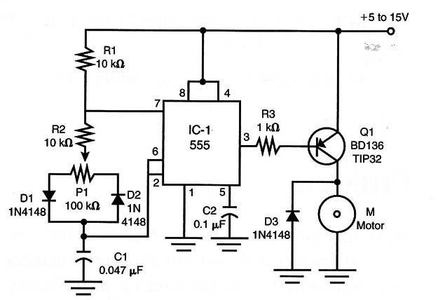
By using this circuit, it is possible to keep the frequency almost constant even through variations occur in the duty cycle.
This configuration is better than the one we had suggested as the basic project. The output transistor can be a medium-power PNP type, such as the BD136 or a Darlington, if you want to control powerful motors.
Practical Circuit
IC1 - 555 timer IC
Q1- -l BD136 or TIP32 PNP silicon power transistor
D1, D2, D3 - 1N4148 or 1N914 general-purpose silicon diodes
R1, R2 - 10 kohm x 1/8-watt resistor (brown, black, orange)
R3 - 1 k ohm x 1/8-watt resistor (brown, black, red)
P1 - 100 kohm potentiometer
C1 - 0.047 to 0.47 µF capacitor
C2 - 0.1 ,uF capacitor
PWM Controlled by.Light
Another interesting idea is to build a robot that can follow the light (or avoid a light) source. The potentiometers are replaced by light-dependent resistam (LDRs) and mounted in an arrangement like the one shown in Figure 15.
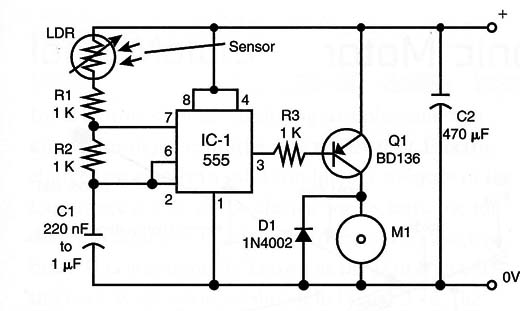
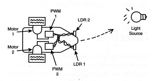
The amount of light falling onto the sensor determines the speed of each motor and then the direction of the movement of the robot. Depending on the way the sensors are placed, the robot will follow or avoid the light, as shown in Figure 16.
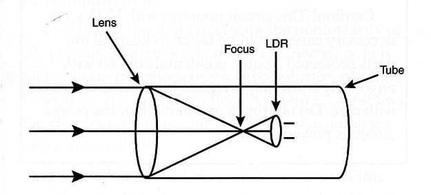
To get more directivity and sensitivity for the sensor, you can mount them onto opaque cardboard having a convergent lens in the front, as shown in Figure 17.
Controlling by a Computer
The circuit shown in Figure 18 can be used to convert the logic level in the input/output (I/O) port of a computer to a voltage.
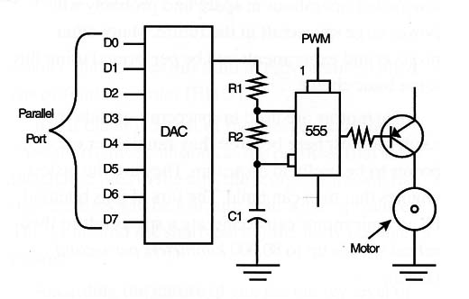
This digital-to-analog converter (DAC) can be used to control the speed of a DC motor when coupled to the PWM control.
You also can use the outputs of a microcontroler to control many circuits like this in a robot or other project.
The Technology Today
PWM controls are used in industrial machines to keep the speed under predetermined values. The precision of the control and the use of feedback sensors to monitor the speed make this kind of circuit ideal for those applications.


