For information about the operation of PWM controls see the article MEC006E – Linear and PWM Motor Control in this site.
PWM Basic Control Using the 4093 CMOS IC
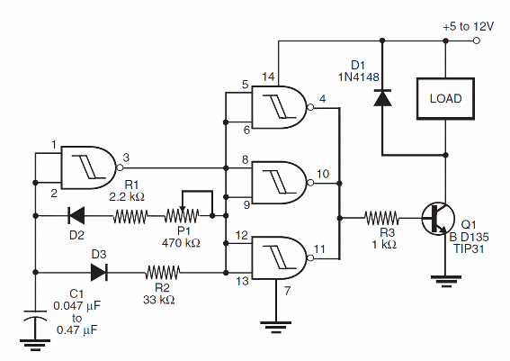
The circuit shown in Figure 1 is a simple PWM control for dc motors up to several amperes, depending on the transistor chosen for Q1.

The circuit is formed by a low-frequency oscillator using one of the four gates of a 4093 IC.
The other three gates are wired as a buffer/amplifier to drive the output transistor.
Capacitor C1 determines the frequency range and must be chosen to suit the motor.
In some cases, some motor vibration can occur if an improper capacitor is used.
Resistor R1 determines the smallest pulse width applied to the motor. and the ratio between P1 and R2 sets the maximum duty cycle of the control.
Experiments with R1 and R2 must be conducted to find the best operating range for any motor.
D1 and D2 can be any general-puipose silicon diode such as the 1N914. 1N4148.or even 1N4002.
Pin 1 of the IC can be used as an external enable input.
The circuit can be used with Darlington transistor if you replace R3 with a 4.7 k Ω resistor.
PWM Control Using the 4001/4011 CMOS IC
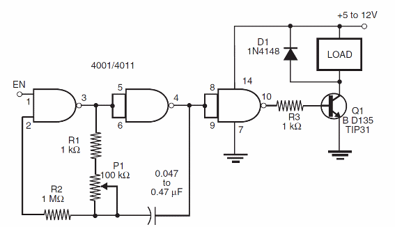
The circuit shown in Figure 2 is formed by a low-frequency oscillator using two of the four gates of a 4001 or 4011 CMOS IC.

The output transistor (Q1) is chosen to match the characteristics of the dc motor to be controlled.
If a Darlington transistor is used. R3 can be increased to 4.7 k Ω.
P1 determines the power range. R1 and R2 must be chosen to give the desired power range.
C1 also depends on the motor and is chosen to avoid Vibrations during motor operation.
The other two gates of a 401 l or 4001 IC can be used in other applications, since they are functionally independent.
This circuit can also be altered to use a power MOSFET to replace Q1.
The gate of the transistor is then plugged directly to the output of the three gates of the IC.
This circuit can be also enabled by yhe output of microcontrollers as the Arduino, MSP430 and PICs.
In this case, these circuit don´’t use the PWM functions of the microcontrollers, but only the on/off functions.


