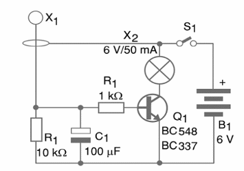
The operation principle is the next: housed inside a plastic box, it can be carried by a robot, a bicycle, or another vehicle. The device has a small lamp and a pendulum sensor (X1). In normal conditions, the pendulum does not make any contact with the loop. But in the case of a change in the speed (breaking) or balance, contact is made, triggering the circuit. This causes the lamp to glow for some seconds due to the charge stored in the capacitor.
The loop and the pendulum must be rigid enough to not trigger the circuit with the normal balance or a light change in the speed. The circuit cannot trigger when passing through small ground undulations or holes.
The sensor must be positioned in a manner that it triggers only when the vehicle brakes. The device is powered by common cells and, by replacing the lamp, you can use a Jumbo Red LED. Connect it in series with a 33 ? to 100 ? resistor. Figure 1 shows the diagram of the device.

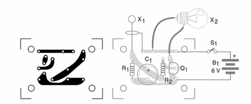
Figure 2 shows how the components can be placed on a printed circuit board. Since the circuit is not critical, the components can also be assembled on a terminal strip;

The lamp is a 6 V x 50 mA type. Powerful lamps are not recommended, since the circuit is powered by AA cells. If you intend to use 100 mA or 200 mA lamps, powering the circuit by C or D cells, replace the transistor with a BD135, BD137 or TIP31. You may probably have to increase the capacitor C1.
The sensor is made using uncovered copper wire 16 or 18 AWG. The ballast can be a small metal ball. Testing is very easy. Power the circuit and touch the sensor to make the pendulum contact the loop. The lamp will glow for some seconds. Once the operation of the device was verified, you can install it.
Semiconductors:
Q1—BC548 or equivalent—general purpose silicon NPN transistor
Resistors: (1/8 W, 5%)
R1—10 kΩ—brown, black, orange
R2—1 kΩ—brown, black, red
Capacitors:
C1—47 μF to 470 μF x 6 V—electrolytic
Other:
X1—sensor—see previous text
X2—6 V x 50 mA — incandescent lamp
S1—On/off switch
B1—6 V—4 AA cells with holder
Printed circuit board, plastic box, wires, solder, etc.


