Obs. This article was published in a Brazilian magazine and translated into English to be part of my book Mechatronics for the Evil Genius (TAB -2006).
Robots and mechatronic devices, because they involve programmed operations, can be controlled by PLCs. Of course, inexpensive PLCs can be used in experimental robots or can learn the special language used to program the robots.
However, we propose the construction of a very simple PLC to teach the evil genius how PLCs work and how they can be used to control small mechatronic automated devices.
The circuit does not need special computer language to be programmed because the program is made for specific hardware. The number of operations that can be performed is limited but is great enough to make interesting devices.
Objectives
Learn how a PLC works.
Use a PLC to control simple tasks.
Create automatic routines controlled by a PLC.
How it Works
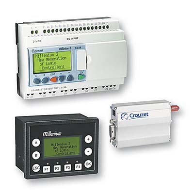
A real PLC is a small box containing a microcontroller as well as inputs and outputs, as shown in Figure 1.
Wired to the inputs are sensors or a keyboard that sends information to the PLC about an external situation that should be considered while the program is running.
The microcontroller receives this information, and while the program is running a PLC determines the next move to be made. For instance, it might be programmed to turn off a motor if a lever is low or turn on the motor if the lever is high.
The decisions are dependent on many variables. The motor is turned on when the lever is low, but the motor can also be turned on by a key or from some other kind of actuator.
The outputs send the appropriate signal to the device(s) to be commanded.
The program is written in a special language and stored in the PLC’s memory. Many standard languages are adopted for use by the different types of PLCs.
The PLC produces signals to respond to the sensors that are activated according to a program stored inside its memory.
The most important characteristic of a PLC is that it can be used to control any process. As long as we know what we want from the machine, we can program that into the PLC. PLCs can be used to control everything from small automations in a home to complex industrial machines.
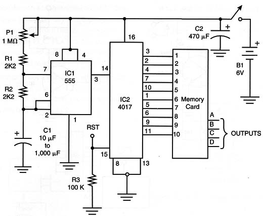
Our project is not a real PLC, although it operates following the same principles. To make it easy to build using inexpensive parts, the circuit is very simple, as shown by Figure 2.
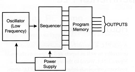
The input block controls a simple oscillator that can be programmed to determine the speed of the process. This block uses a 555 integrated circuit (IC), and C1 determines the range of speeds for the PLC.
Values between 10 and 1,000 µF are recommended. Using a 1,000 µF capacitor, the execution time of each line of the program when P1 is in the maximum resistance is about 15 minutes each.
The oscillator is controlled by an external sensor and has two additional inputs for commands: an enable (EN) input that stops the oscillator and a reset (RST) input that returns the count of the Johnson counter in the second block to zero.
This block provides pulses to the second block, a Johnson counter with 10 outputs, activated in the 1 of 10 mode. A 4017 IC is used and it determines the size of the program memory: 10 lines or 10 words.
The number of bits depends on the following block.
The next block is the program memory and is made with diodes. This block is formed by horizontal lines that are wired to the outputs of the sequencer block and vertical lines that correspond to the outputs.
When we want a high logic level in the second line to cause the first and second outputs to go high, simply connect the diodes, as shown in Figure 3.
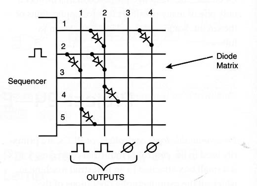
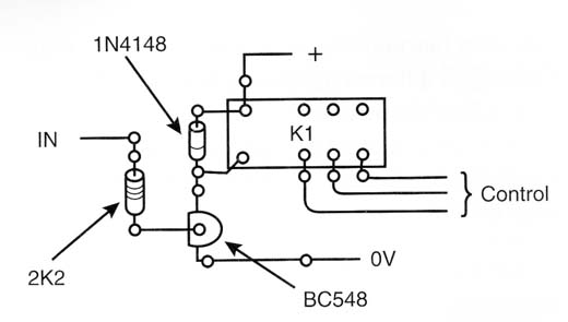
So the number of diodes and their positions determine when each output is activated by one of the program lines. The diodes are mounted in a small printed circuit board (PCB) and plugged into a connector. The board is the program. The outputs can activate relays or other circuits as suggested by Figure 4.
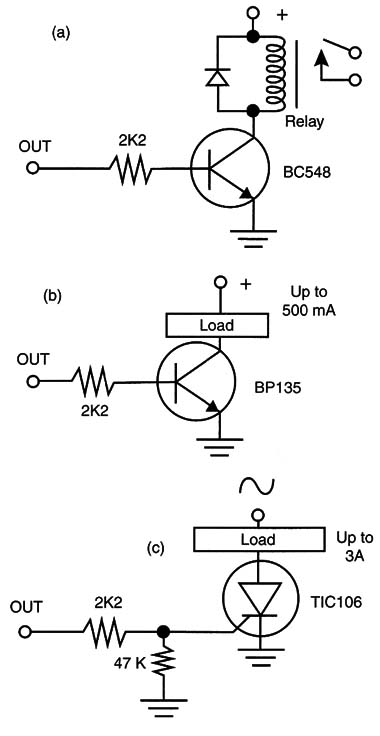
The circuit can be powered by a 5- to 12-volt source according to the loads to be controlled by the outputs. But remember that the outputs of the matrix can provide only 0.88 mA when powered by a 5-volt supply, 2.25 mA with a 10-volt power supply, and 8.8 mA with 15-volt supply. These currents determine the number of output lines for the PLC.
Building
Figure 5 shows the schematic for the PLC.
The circuit can be mounted on a PCB as shown in Figure 6.
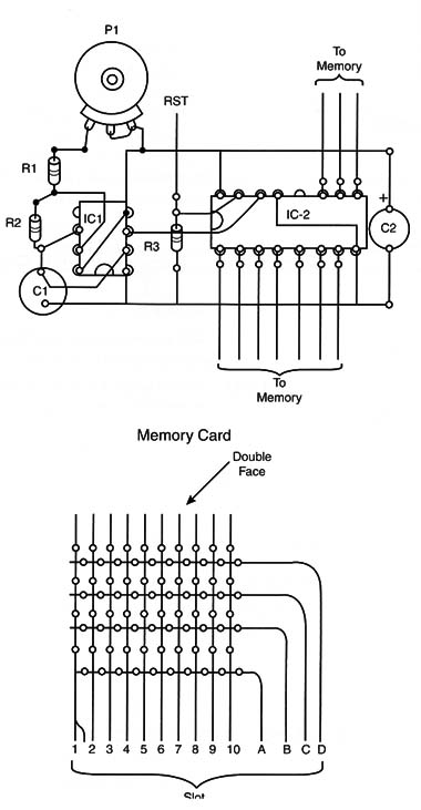
In the same figure, we show the details of the program board where the diodes are soldered according to the program. The reader must have more than one of these boards to make different programs for the PLC.
The circuit can be powered by AA cells or a power supply with voltages ranging from 5 to 12 volts. Figure 7 shows a PCB for relays.
When mounting, take care with the polarized components such as the ICs, diodes, electrolytic capacitor, and the power supply.
Testing and Using
To test your PLC, you can power an experimental circuit formed by light-emitting diodes (LEDs) plugged into the outputs, as shown in Figure 8.
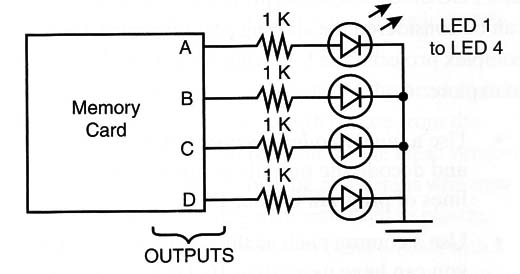
After inserting the program card (the board with the diodes) and powering the circuit, adjust P1 to the minimum resistance. The LEDs will glow according to the program determined for the diodes. Once you verify the operation, you can use your PLCs to control automated devices or for demonstrations.
IC-1 - 555 IC timer
IC 4017 - complementary metal oxide semiconductor (CMOS) IC
D1 to Dn - 1N4148 general-purpose silicon diodes (see text)
P1 - 1 M ohm trimmer potentiometer
R1, R2 - 2.2 k ohm - 1/8-watt resistors (red, red, red)
R3 - 100 k ohm - 1/8-watt resistor (brown, black, yellow)
C1 - 10 µF to 1,000 ptF - 12-volt electrolytic capacitor
C2 - 470 µF - 16-volt electrolytic capacitor
B1 - 4 AA cells or other power supply totaling 6 volts (see text)
Power supply, PCB, slide connector (according to the lines of program and outputs), wires, solder, etc.
Cross Themes
Students in industrial automation and engineering courses study PLCs, but, of course, they study these devices in much greater detail. In high-school-level courses, it is possible to include lessons on this type of device in elective subjects that study mechatronics.
The idea is to study a simple automated process that could be easy to understand even for persons who don’t have the necessary knowledge in electronics.
Therefore, you can use this PLC in cross themes such as the ones suggested in the following list:
Study how an automated process functions.
Make automated devices for demonstrations.
Teach applications of digital logic.
Applications
Addin a Sensor-Activated Switch
Figure 9 shows how to modify the oscillator to operate as a monostable device triggering the counter from the signals of a sensor.
Figure 9 – Adding a monostable
Each time the sensor is closed the monostable device produces a pulse and the counter advances one line in the memory. Thus, the sequence of operations programmed in the memory is controlled by the sensor. The sensor can be a reed switch, a pushbutton, or another kind of on/off sensor.
Adding More Logic
An interesting way to add more logic to the PLC is shown in Figure 10.
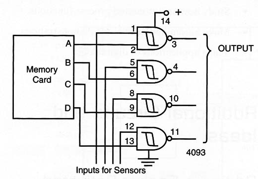
Four gates of a 4093 are added to the circuit to make the outputs dependent on the logic levels of inputs A to D. These inputs can be connected to sensors, logic arrays, or other devices to command the PLC.
Expanding the Memory
Finally, you can have more than 10 lines of program memory in your PLC using two or more 40175, as shown in Figure 11.

Suggestions
The PLC described in this project is very simple but can be considered the starting point for much more complex projects. The following is a list of some ideas to explore:
Use a binary coded decimal (BCD) counter and decode the outputs in order to have 16 lines of program in your PLC.
Use a counter such as the 4020 (16 k) so that you can have more than 16,000 lines of program. Of course, you’ll need a decodification block.
Try to use RAM instead of a diode matrix and program it using a computer.
Develop an automated device controlled by your PLC. Try to add it to the autonomous robot giving it some intelligence.


