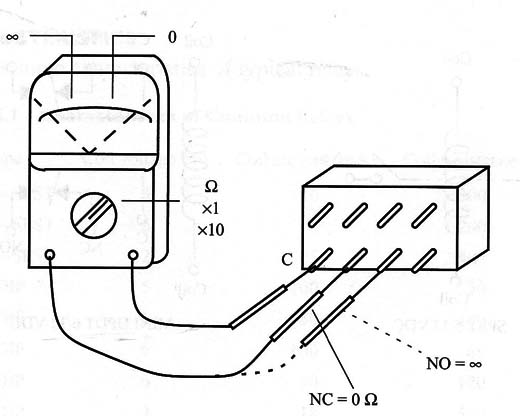
a. Contact terminals. The contacts of a relay have a near-zero ohmic resistance when closed and inlinite resistance when open. Using a multimeter in any resistance (Ω) scale, we can identify the contacts that are common (C), normally open (NO), and normally closed (NC) as shown in Fig. 1.

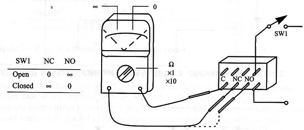
If this procedure allows us to accurately identify the common terminal, we may power up the coil of the relay to turn it on and make new measurements. The new conditions of measurement are as shown in Fig. 5.2.

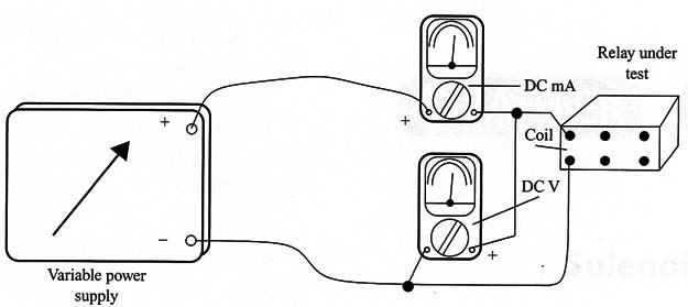
b. Triggering characteristics. To determine the triggering characteristics of a relay, we need a power supply with an output that is at least sufficient to drive the coil. Figure 3 shows a simple circuit that can be used to test relays with voltage coils up to 24 V.

Multimeter M1 is adjusted to measure DC voltages (VDC), and multimeter M2 is adjusted to measure DC currents (DCmA up to 500 mA or more).
Procedure
1. Adjust P1 to 0V at M1.
2. Open P1 slowly to raise the voltage across the relay, observing the load connected to the relay contacts.
3. When the load turns on, you can read the trigger voltage of the relay on M1, and the trigger current on M2.
4. Working again with Pl, reduce the voltage until the relay turns off the load.
5. At this point, you can read the hold voltage in M2 and the hold current in M2.
Note that the small difference in the trigger voltage and the hold voltage is an important characteristic to be considered when using relays. This hysteresis is your guarantee that the contacts will not bounce when the relay turns on and off.
Obs.: In some cases, is not necessary to connect a load to the contacts of the relay under test. The “click” produced by the relay when turning on and off may be enough to allow you to verify its operation.
ADDITIONAL INFORMATION
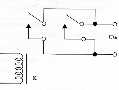
a. Connecting the contacts to control high-power loads. If you need to control a load that is rated for currents above the limit of the contacts of your relay, and the relay has more than one pair of contacts (e.g., DPDT), the contacts can be wired in parallel as shown in Fig. 4.

Some manufacturers recommend that you wire the contacts in parallel, based on the idea that is more important to increase the gap between the contacts than to increase the effective surface when controlling high currents.
b. Debouncing. Problems can arise when inductive or capacitive loads are controlled and operation is disrupted by contact bounce. Some circuits, found in the site, can be used to solve such problems.


