The CMOS integrated circuits have an extremely high input impedance which gives them unparalleled sensitivity.
In fact, this excessive sensitivity is even a danger, since the mere touch of the fingers of a person who has previously walked on a carpet on a dry day, and therefore acquired a strong static charge, can permanently damage it.
With the use of this sensitivity, avoiding excesses, CMOS integrated circuits can be used as network-induced signal detectors (snores), small transmitter signals, high voltage transients and also static charges accumulated in various objects.
If you use as an antenna a rod on the roof of your house and the approaching charged clouds, indicative of storms will trigger your detector.
The detector described is powered by standard batteries or a 9 V battery cell and emits a continuous tone of great volume when a load or strange signal is detected by its small antenna.
HOW IT WORKS
The basis of our design is a 4093 type CMOS integrated circuit consisting of four stand-alone NAND (Non-E) gates.
These gates, as we have seen in many articles in this site, can be linked to perform their basic logic functions but also as inverters, digital amplifiers and even oscillators capable of operating in the audio and RF range up to a few megahertz.
In our circuit the 4 gates are used in 3 different functions:
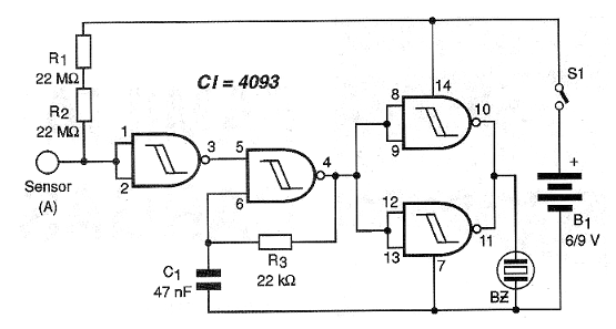
The first gate, which has access through pins 1, 2 and 3 (1 and 2 are the inputs and 3 the output) functions as an inverting amplifier.
High-value resistors R1 and R2 keep the input of the integrated circuit high enough so that its output remains low.
This way, the audio oscillator formed by the second gate (access on pins 5, 6 and 4) is inhibited.
The frequency of this oscillator, within the audio range, is determined by the capacitor C1 and resistor R3. The reader can change R3 by choosing values between 15 k ohm and 100 k ohm if you want a high or low pitch sound for alert.
The presence of the signal on the antenna causes the logic level of the input of the first gate to be changed. This causes its output to go to the high logic level and thus the audio oscillator formed by the second gate comes into action.
The audio oscillator signal in action is amplified by the two other gates (pins 8 to 13) which then operate as buffers, isolating the oscillator from the output, and also as digital amplifiers.
The output of the digital amplifiers is taken to a ceramic transducer which then converts the electrical signal into audible sound.
The circuit is supplied with voltages of 6 to 9 volts of regular batteries or battery and the total consumption of the device when it is quietly below 2 mA (tip).
ASSEMBLY
In Figure 1, we have the complete diagram of the device.

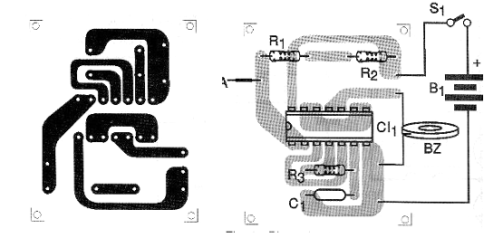
In Figure 2, we have the arrangement of the components on a printed circuit board.

The components have their minimum specifications given in the list of materials.
The antenna is a simple piece of ordinary wire which can be without cover or with cover, since the device does not operate by contact, but by induction. This antenna should be 10 to 20 cm long depending on the sensitivity you want. For a remote connection of the antenna, shielded wire must be used with the mesh connected to the (+) power supply of the unit.
The transducer is of the ceramic piezoelectric type, but even a piezoelectric tweeter or a headset capsule without the internal transformer can be used.
An interesting possibility of design change is to exchange R3 for a resistor of 2.2 M ohm and C1 for a capacitor of 470 nF.
In the output, we connect a series LED with a resistor of 1 k ohm, observing its polarity according to the level of signal with which we want it to light.
Instead of having an audio signal on detection, we will have a blinking LED.
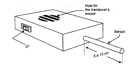
The whole assembly fits easily into a small plastic box that looks like the one shown in Figure 3.

Observe the existence of holes in the box for sound output of the transducer. The antenna can be connected via a terminal which would facilitate its removal for transgate.
TEST AND USE
To test the unit simply plug in its power and bring the antenna closer to any source of noise, such as a power cord.
Another possibility is to hold the wire with your fingers or even close to a plastic object (pen, comb or ruler) which has been rubbed in wool or silk in order to acquire electric charge.
The sensitivity of the device can be increased by adding one or two 22 M ohm resistors in series with R1 and R2.
We note that direct contact of the antenna (if it is peeled) with objects having high static charges should be avoided as this may cause the integrated circuit to burn.
Erratic triggering means the presence of strong sources of noise. To decrease the sensitivity, simply remove R1 from the circuit by holding only R2.
IN THE LAB
In the high school electricity and technical course laboratory, this device can be used as a sensitive electronic electroscope, much more sensitive than conventional types of sheets.
The polarity of the load, which will determine the trigger of the circuit, can be programmed quite interesting experiments of demonstrations.
An adaptation that can be made in the original design is the connection of a relay triggering step to the output. In this case, the circuit can be used to trigger an alarm in the presence of static or transient loads.
Semiconductors:
CI-1 - 4093 - CMOS integrated circuit
Resistors: (1/8 W, 5%)
R1, R2 - 22 M ohms - red, red, blue
R3 - 22k ohm - red, red, orange
Capacitors:
C1 - 47 nF - ceramic or polyester
Several:
BZ - Ceramic transducer - see text
S1 - Single switch
B1 - 6 to 9 V - 4 batteries or battery
A - antenna - see text
Printed circuit board, mounting box, connector for battery or battery holder, wires, welding, etc.


