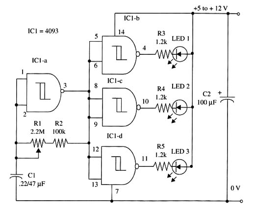
If the oscillator section is not good (IC 1-a), the LEDs will not flash. But if the oscillator section is good and one of the other gates not, the corresponding LED Will not flash but the other LEDs will flash at a rate of about 1 Hz. A schematic diagram of the 4093 IC test is shown in Fig. 1.

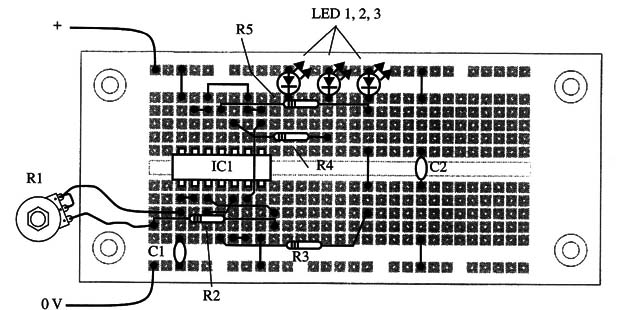
The circuit is mounted on a solderless board as shown in Fig. 2.

Proper positioning of polarized components, such as the LEDs and capacitor C2, must be observed.
IC1 - 4093 CMOS integrated circuit
LED1, LED2, LED3 - Common red, green, or yellow LEDs
R1 - 2,200,000 ohm, 1/4 W, 5% resistor
R2, R3, R4 - 1,200 ohm, 1/4 W, 5% resistors
C1 - 0.22 µF ceramic or metal film capacitor
C2 - 100 µF, 16 WVDC electrolytic capacitor


