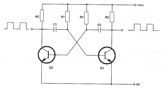
The astable multivibrator is formed by two bipolar transistor wired as shown in figure. This circuit produces a square wave with duty cycle depending on the conducing time of each transistor. Equivalent configurations can be made based in FETs or even in tubes.

Formula 1
Conduction time:
tp = 0.69 x R x C
Where:
tp is the conduction time of one transistor in seconds (s)
R is the resistance in ohm (Ω)
C is the capacitance in farads (F)
Note: For Q1 the conduction time tp1 is given by R1 and C1 and for Q2 the conduction time tp2 is given by R2 and C2.
Formula 2
Frequency:
f = 1 / (tp1 + tp2)
f = 1 / 0.69 x (R1 x C1 + R2 x C2)
Where:
f is the frequency in hertz (Hz)
R1, R2 are the resistances in ohm (Ω)
C1, C2 are the capacitances in farads (F)
Derivated formulas:
Formula 3
Square wave oscillator (50% duty cycle) - R1 = R2 = R and C1 = C2 = C
f = 1 / (1.38 x R x C)
Where:
f is the frequency in hertz (Hz)
R is the resistance in ohm (Ω)
C is the capacitance in farads (F)
Formula 4
Frequency as function of conduction time when R1 = R2 = R and C1 = C2 = C
f = 1 / (2 x tp)
Where:
f is the frequency in hertz (Hz)
tp is the conduction time in seconds (s)
Application example:
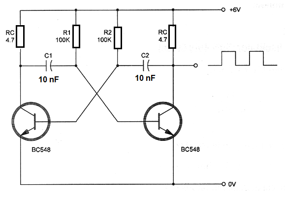
Determine the frequency of the free-runing multivibrator with the schematic diagram shown in figure.

Data:
R1 = R2 = 100 kΩ = 10 x 103
C1 = C2 = 10 nF = 0.01 ? x 10-6
Using formula 3:
f = 1 / (1.38 x 10 x 103 x 0.01 x 10-6)
f = 1 / (0.138 x 10⁻³)
f = (1 / 0.138) x 103
f = 7.246 x 10³
f = 7.246 kHz


