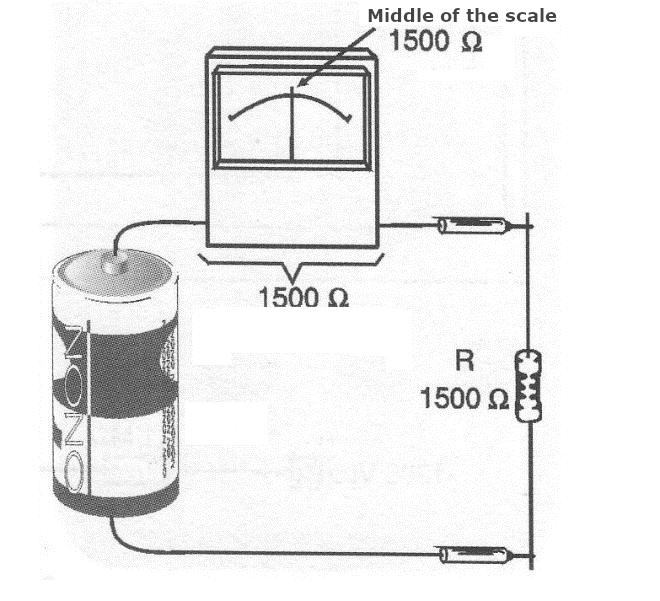
An ohmmeter is nothing more than a resistance meter. It is already included in multimeters when we select the ohm scales (resistances).
In a traditional application, for an analogue instrument, we have a power supply (usually a battery), a resistor, and a trim-pot (to adjust the full-scale or zeroing) and the metering instrument itself.
Thus, we have a typical circuit, as shown in Figure 1.
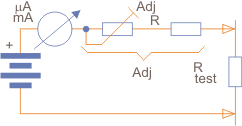
When the probes are joined together, and therefore the resistance between them is zero, the electric current in the instrument is set to full-scale (maximum). We then have the zero of the scale.
When the probes are separated, the current is zero, corresponding to the beginning of the scale or infinite. For the middle of the scale, the electric current is given by the adjustment resistance.
When the adjustment resistance is equal to the resistance between the probes, the current in the instrument will be half of the full-scale. We then have an inverted non-linear scale for this type of instrument, as shown in Figure 2.

We can reason for intermediate values as follows: Assuming that the instrument taken as an example is 0-1 mA.
Under these conditions, if the supply voltage is 1.5 V (one battery), for the total electric current (full-scale), we need the circuit to have a total resistance of 1,500 ohms.
If we are going to measure a resistance of the same value, that is, 1,500 ohms, the resistance is placed in series with the circuit, as shown in Figure 3.
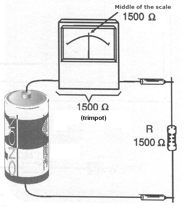
The total resistance will become the sum, that is, 3,000 ohms, so the current indicated by the instrument will be half of 1 mA, or 0.5 mA (500 uA). The instrument will have its needle moved to the centre of the scale. In this instrument, the scale can be made as shown in Figure 4, with a resistance of 1,500 ohms in the centre.
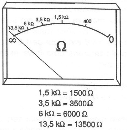
For the resistance of 15,000 ohms, for example, which corresponds to an external resistance of 13,500 ohms (1,500 ohms are of the instrument), we will have a current of 1/10 of the full-scale.
The point that causes 1/10 deflection corresponds to 15,000 ohms. Note that we can quickly get readings in the middle-range of the scale corresponding to roughly 500 ohms to 5,000 ohms.
Note that, for the basic instrument, resistance is measured by circulating an electric current through the test circuit, a process that requires an external battery for its operation.
The adjustment trim-pot is important because the trend is that the electric current decreases with the natural depletion of the battery, so we do not get the value zero joining the probes. With the trim-pot, the measurement can be achieved by adjusting the zero of the scale.
The trim-pot that we find on the resistance scales of multimeters is named "zero adj" or "zero adjustments".
How to Calculate
A typical question that appears on exams, tests, etc., is to calculate the value of R, the resistor in series with the instrument, to obtain an ohmmeter, as stated in the introduction.
So, we have two types of problems:
a) Using the instrument directly.
b) With a shunt for scale magnification.
Let's analyze the two cases:
a) Direct calculation:
In this case, we have the basic circuit sown in Figure 5.
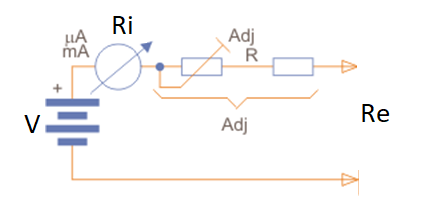
In this case, we have:
V = Voltage of the battery used as the power supply (1.5 V)
Ri = Internal resistance of the instrument
R = Resistance of the adjustment circuit (to be calculated)
Re = external resistance to be measured
I = Full-scale electric current of the instrument
For the adjustment resistance R calculation, we initially set Re = 0.
We then apply the formula:
R = V/I - Ri where (1)
V is the battery voltage.
I is the full-scale current.
Ri is the instrument's resistance (in some cases, it can be neglected).
Having found R, we see that this value is the sum of the adjustment resistance and the fixed resistor in series.
In practice, it is interesting that the calculated resistance is reached halfway through the trim-pot setting to compensate the battery voltage value as it depletes.
So, if the calculated value is R, we use a trim-pot of that value altogether with a resistor of half of R, or R/2. Thus, at the maximum of the adjustment, we have 1.5R, and at the half of the adjustment, we have R/2, which gives a range of values around the one calculated for the zero position.
Let's take a practical example:
Calculate the value of the trim-pot and the resistor in series (adjustment resistance) for an ohmmeter that uses a 1 mA full-scale milliammeter and is powered by a 1.5 V battery. The internal resistance of the instrument is 300 ohms.
Procedure:
We have:
V = 1.5 V
Ri = 300 ohms
I = 0.001 A (1 mA)
Assuming Re = 0, we can apply formula (1).
R = V/I - Ri
R = 1.5/0.001 - 300
R = 1500 - 300
R = 1200 ohms
In practice, we can employ a 1k trim-pot (commercial value) with a 470 ohms or 560 ohms resistor in series (commercial value).
Once the instrument is zeroed by adjusting the trim-pot, we see that this represents a resistance of 1,500 ohms (1,200 ohms plus 300 ohms of the internal resistance) when we join the probes together. It will cause the current to be at full-scale: 1 mA.
Note that if this instrument measures resistance of 1,500 ohms, the current will be 0.05 mA, or half the full-scale, as shown in Figure 6.
With that, we will have a scale as shown in Figure 7, where other values ??can be inscribed.

b) Using shunt to scale up:
Note that the middle of the scale corresponds to a resistance of 1,500 ohms in the example given.
As the resistance scales with this type of indication are logarithmic, it is easy to understand that the higher accuracy is between a little more than 2/3 of the scale and zero, that is, for the smaller resistance range.
If we want to have more accurate readings, depending on the resistance range, we can change the middle of the scale with the help of a shunt, as shown in Figure 8.
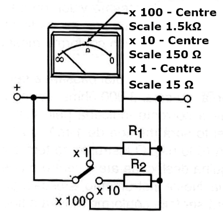
If a shunt that multiplies the instrument's range by ten is placed in the circuit so that, in the example, it goes from 0-1 mA to 0-10 mA, we will already have other conditions for measuring resistances.
Note that for a supply voltage of 1.5 V (which is maintained), the total resistance of the instrument will be:
R = 1,5/0,01
R = 150 ohms
The full-scale current will be obtained by joining the probes together with a total resistance of 150 ohms. The centre of the scale will be obtained when we have double this resistance, which now means a total resistance of 300 ohms, or more 150 ohms between the probes.
On the new scale, the new centre will be 150 ohms, and the 1/10 of the deflection will also be divided by 10, thus corresponding to 1,350 ohms. With another current multiplication, we can reach the centre of the scale of 15 ohms, but this is not convenient, as the current used in the test will be high, which may overload the circuit in test and cause rapid battery depletion.
And if we want to have higher resistance scales?
One way is to operate with higher voltages. If we use 15V instead of 1.5V, for example, we will have a new basic scale of:
R = 15/0,001
R = 15 000 ohms
The value will be 30,000 ohms for half of the scale, which corresponds to an external resistance of 15,000 ohms.
Some more sensitive instruments, which have resistance scales with centres up to 500,000 ohms, use two batteries, one 1.5V and one 15V for their resistance scales. The 1.5V is for lower scales, and the other is for higher scales.
The combination of scales in a single instrument can also be accomplished by employing keys or changing the pins to which the probes are connected.
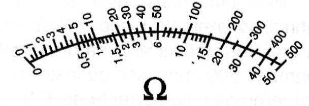
We then achieve the "multi-ohmmeter", a resistance meter with several scales. In Figure 9, we have a typical scale of a multi-ohmmeter with centres at 7.5k ohms and 75k ohms.
These settings are adopted in common analog multimeters with various resistance scales. To calculate shunts, see our article: MA231E.

