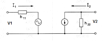
The hybrid parameters were developed by transistor manufacturers to indicate the values of their internal elements. Using hybrid parameters calculations involving transistor circuits can made easier. Figure bellow shows the equivalent circuit for such hybrid parameters.

Definitions:
The hybrid parameters in the circuit shown above are defined as follows:
h11 input impedance with short-circuit output
h12 reverse open-circuit voltage amplification factor
h21 forward short-circuit current amplification factor
h22 output admittance with open-circuit input
Formula 1
Input impedance:
h11 = V1 / I1 para V2 = 0
Formula 2
Reverse open-circuit voltage amplification factor:
h12 = V1 / V2 para I1 = 0
Formula 3
Forward short-circuit current amplification factor (?)
h21 = I2 / I1 para V2 = 0
Formula 4
Output admittance:
h22 = I2 / V2 para I1 = 0
Where:
V1 is the input voltage in volts (V)
V2 is the output voltage in volts (V)
I1 is the input current in amperes (A)
I2 is the output current in amperes (A)
Derivated formulas:
Formula 5
Input voltage:
V1 = h11 x I1 + h12 x V2
Formula 6
Output current:
I2 = h21 x I1 + h22 x V2
Formula 7
Determinant h:
det h = h11 x h22 - h12 x h21
Where: det h is the determinant formed by the hybrid parameters as follows:
det h = 
TABLE - Letter Symbols and Abbreviations for Transistors
|
Symbol |
Term |
|
Det h |
Determinant h |
|
Gi |
Current gain |
|
Gv |
Voltage gain |
|
Gp |
Power gain |
|
h11 |
Input impedance with short-circuit output |
|
h12 |
Reverse open-circuit voltage amplification factor |
|
h21 |
Forward short-circuit amplification factor |
|
h22 |
Output admittance with open circuit output |
|
I1 |
Input current |
|
I2 |
Output current |
|
Ib |
Base current |
|
Ic |
Collector current |
|
Ie |
Emitter current |
|
RG |
Generator resistance |
|
RL |
Load resistance |
|
V1 |
Input voltage |
|
V2 |
Output voltage |
|
Vbc |
Voltage between base and collector |
|
Vbe |
Voltage between base and emitter |
|
Vce |
Voltage between collector and emitter |


