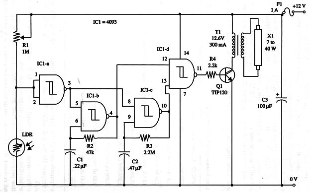
Operation is the same as Project ART061E except as affected by the transposition of the LDR with the potentiometer R1.
The circuit is powered from a 12 V car battery, and the fluorescent lamp can range from 7 to 40 W. The flash rate can be altered by changing C2 and R3.
Current drain depends on the transformer and the fluorescent lamp, ranging from 100 mA to 400 mA.
The sensor and the fluorescent lamp can be installed as far as you want from the device, but they should be separated to avoid feedback.
A schematic diagram of the Light Activated Fluorescent Flasher is shown in Fig.1.

The positions of the polarized components (electrolytic capacitor, integrated circuit, and transistor) must be observed. Transistor Q1 must be mounted on a heatsink.
The power supply is a rechargeable battery (NiCad, for instance) or a car battery. The transformer is the same as the one used in Project ART061E. Installation details are as given in that project
IC1 4093 CMOS integrated circuit
Q1 TIP120 NPN Darlington power transistor
LDR CdS photocell, Radio Shack 276-1657 or equivalent
T1 12.6 V, 300 mA, Radio Shack 27 3-1385 or equivalent transformer, primary 117 Vac
X1 7 to 40 W fluorescent tube
R1 1,000,000 ohm potentiometer or trimmer pot
R2 47,000 ohm, 1/4 W, 5% resistor
R3 2,200,000 ohm, 1/4 W, 5% resistor
R4 2,200 9, 1/4 W, 5% resistor
C1 0.22 µF ceramic or metal film capacitor
C2 0.47 µF ceramic or metal film capacitor
C3 100 µF, 16 WVDC electrolytic capacitor


