This circuit was originally included in my book Mechatronics for the Evil Genius (TAB 2006) to be part of the article Ionic Motor. See more about the Ionic Motor in this site.
The circuit is very simple as you have to mount only the receiver. The transmitter is simply a flash-light, and the receiver has no critical parts or complicated adjustments. Of course, the range is limited to the light of the flashlight and the focusing system in the receiver, but in good conditions you can control a model placed at distances of up to 10 meters. Additional applications for the project will be suggested throughout this project.
Objectiver
Control models and automatic devices using a light beam.
Study how photosensors work.
Design projects that are sensitive to light or dark such as traps, intrusion detectors, or other automated devices.
Apply the circuit for these automated devices to experiments in sciences.
The sensor
The sensor used in this project is a light-dependent resistor (LDR). This device is also called a cadmium sulfide (CdS) cell from the material used in its fabrication.
The LDRs, such as the ones shown in Figure 1, present a very high electric resistance when in the dark. But when illuminated, their resistance of many megΩ falls to hundreds or tens of Ω, leaving the current to flow across them.
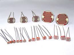
They are very sensitive at detecting amounts of light that even the human eye can’ detect in normal conditions. Although they are sensitive, they are not as fast as other electronic detectors such as photodiodes and phototransistors. For our purposes, they are ideal because they are inexpensive, easy to find, and easy to use.
The Project
In our basic light beam project, the circuit triggers a relay when a light beam is focused on the sensor (LDR). Upgraded versions will time the action of the relay or give a bistable action. The version chosen by the evil genius will depend on the application he or she has in mind.
The operating principle is very easy to understand: When the sensor detects the light, its resistance falls, and the current can flow across the base of a transistor. This current is amplified, driving the relay that closes its contacts.
P1 is adjusted to put the transistor on the threshold of conduction with the ambient light. Therefore, any amount of light falling onto the sensor triggers the circuit.
How to Build
Figure 2 shows the schematic for the basic version of the remote control using a light beam.
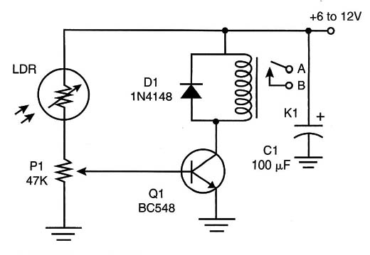
The relay is chosen according to the power supply voltage. The types of relays with Winding currents of up to 50 mA or more are recommended. A simple mounting can be made using a solderless board, as shown in Figure 3.
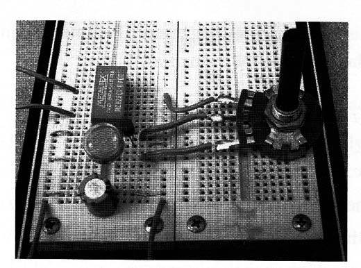
Because the circuit draws relatively low current, it can be powered by the same supply used in the application where the circuit will be installed. The relay in the photo is a universal type with dual inline terminals. If you use another type of relay, you must be sure about the identification of the terminals for the coil and the contacts.
The LDR can be of any size, but it must be round and installed inside a small cardboard tube or other opaque material. A convergent lens can be added to get directivity and increase the sensitivity of the circuit, as shown in Figure 4.
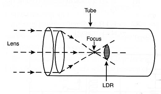
The power supply depends on the voltage rate of the relayªs coil. For instance, if you use a 6 V x 50 mA relay, the power supply can be formed by four AA, C, or D cells. It is helpful to review the specifications so that you use the same supply for the circuit and the rest of the project.
Testing and Using
It is very easy to test your remote control. Power the circuit on and close P1 (put it in the position of minimum resistance). Then point the LDR toward a dark place.
Now, opening P1 slowly, you will hear when the contacts close. Open P1 a little to open the contacts again. Then, focusing the flashlight on the LDR, you will hear when the relay closes the contacts. If you can,t hear your relay, a light-emitting diode (LED) as an indicator can be wired to the circuit, as shown in Figure 5.
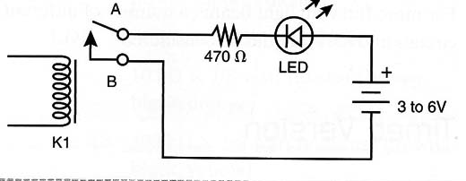
When using the LED, adjust P1 to put the relay near the triggering point. Then the flashlight can trigger the circuit. Remember that the relay will be on only during the time the sensor receives the light.
Q1 - BC548 general-purpose negative-positive-negative (NPN ) silicon transistor
D1 - 1N4148 general-purpose silicon diode
LDR - Any LDR or CdS cell (see text)
P1 - 47 k trimmer potentiometer
C1 - 100 µF x 12-volt electrolytic capacitor
K1 - 6 or 12-Volt x 50 mA relay
Printed circuit board (PCB) or solderless board, wires, solder, power supply, etc.
Cross Themes
A light-beam remote control can be used as an auxiliary device to implement or trigger experiments in many devices. The control can be used to activate devices remotely, including traps, fans, lamps and more. A few suggestions follow:
Close a trap to catch animals
Start dangerous experiments remotely
Turn on and off devices in experiments from a safe distance


