This small transmitter for espionage and other applications emit signals that can be picked up at a distance of 30 meters. Speak into the microphone and hear your voice on a common FM radio. It can also be connected to a telephone line to allow the hearing conversations on a FM radio.
What is the FM Microtransmitter -Transnew-2
Transnew-2 is a FM Microtransmitter which uses only one transistor.
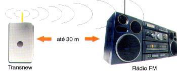
Powered by 2 or 4 standard batteries it can send its signals to an FM receiver (a common radio, a car radio or a stereo system with FM) to a distance of 30 meters. Depending on the setting, Transnew-2 can also be captured by the low TV channels (2 to 5) producing an interference effect that may be used to demonstrate its operating principle. In Figure 1 we show the Transnew operating principle, sending its signals to a radio or sound system which has FM.
The Transnew-2 has a sensitive electret microphone. This microphone is used to capture the voice of those who use the transmitter and also conversations, if left hidden, functioning as a good electronic spy.
The reach depends on several factors such as the existence of interference on site, many obstacles for the sign, or congestion on the FM range (many stations). The two or four batteries that power the device has excellent durability. Another interesting application is like a wireless microphone for events, simply connect the receiver output to a powerful sound system. Finally, the microphone can be removed and its input connected to a telephone line to listen or "clip" as it is called the operation in espionage.
How it works
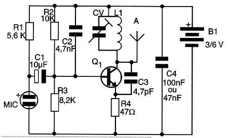
The transmitter is basically a high-frequency oscillator, where the frequency is determined by the resonant circuit L1/CV. This circuit can be set to CV to operate in frequencies between 60 MHz and 108 approximately covering the FM range and a part of the TV range. The feedback that keeps the oscillation comes from the capacitors of 4.7 pF and 100 nF in parallel with the source, it makes its dislocation.
The electret microphone has an amplifier transistor therein, which is polarized by the resistor R1. The signals captured by the microphone pass to the high frequency circuit through the electrolytic capacitor C1. Applied to the base of the transistor, these signals make the modulation, in other words, they make the transmitted signal varies in frequency according to the sound, which is then recognized by the receiver and reproduced through the speaker.
Assembly
In Figure 2 we give the complete diagram of the transmitter.
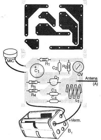
In Figure 3 we have the arrangement of the components on the printed circuit board.
The components should have their terminals inserted into the holes of the board in order to go through the copper side, where they are welded. After welding, the excesses of these terminals are cut, as shown in Figure 4.
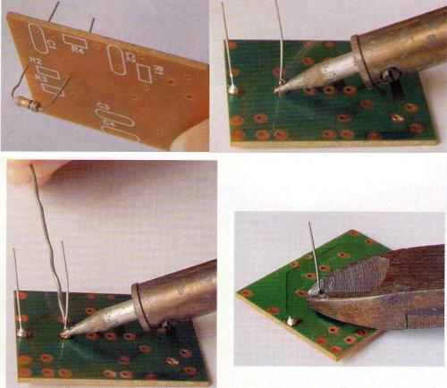
Before starting the assembly, check out all the components, with special attention to the values of the resistors and capacitors. Make the weld quickly so that excess of heat does not damage the components. The following sequence of photos show the assembly step-by-step:
(a) - Fit the resistors and weld them, cutting their terminals (R1 to R4)
(b) - Fit the capacitors and weld their terminals, cutting the excess (C1 to C4) - beware of the values - check out the list of materials for the possible markings.
(c) - Fit the trimmer, carefully and weld their terminals.
(d) - Scrape the coil terminals with a blade, fit and weld them.
(e) - Weld the transistor observing the position of the flat side.
(f) - Fit the electret microphone wires observing their positions and weld them.
(g) - Weld the antenna.
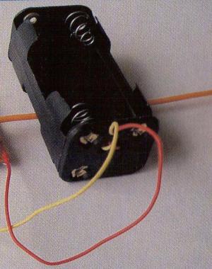
(h) - Weld the battery holder terminals.
Check out all the assembly paying attention to the values ??of the components before testing and adjusting.
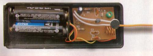
Photo - Transnew-2 built - the set must be installed in a plastic box.
Operational Test and Adjustments
Connect nearby the transmitter a FM radio tuned to a free frequency (between stations) in the extremity of the lower range (near 88 MHz).
Insert the batteries into the transmitter holder, observing the correct polarity.
At this time, depending on your assembly you can hear something on the receiver, indicating that it is oscillating. Placing a hand on the coil you should notice it.
With a small screwdriver (preferably plastic) adjust the CV until you capture the signal. The strong whistle that occurs indicates that the microphone is working. The whistle is called “the acoustic feedback" and it disappears if you move away from the receiver.
Make the tuning of the receiver until you capture the strongest signal while speaking on the microphone.
Retouch this tune until you find a clear frequency.
Check out the reach moving away from the receiver. If the signal "disappears" soon, it is a sign that you tuned on a spurious signal, ie, a frequency with weaker signal which does not correspond to that one which it is actually focusing the maximum signal. Retrace the tune.
To use the transmitter:
To use it as a steering wheel microphone or in communications, always hold the board by its sides and with the antenna in the vertical, avoiding sudden movements. One idea is to install the transmitter in a plastic box in order to facilitate its handling, as shown in Figure 5.
Remove the batteries from the holder when you are not using the transmitter.
For spy work, always leave the antenna in vertical position, away from metal objects which may cause interference. Avoid places subjected to movements because the excessive swing of the antenna causes operational instability, as the random change of the transmission frequency, making it difficult to tune.
The maximum length of the antenna is 40 cm. More than that can cause operational instabilities.
Issues that may occur
The main problems that may occur with the assembly of this transmitter are:
a) Cold weld
The cold weld occurs when the soldering iron is not hot enough, the board surface or the welded component is dirty (greasy or oxidized) and the weld does "not handle." The weld ball is formed, but it is not providing the electrical contact among the components. Like this the current does not go through and the device does not work. Use the welder to reheat all weld points. If this does not work, unmake the suspected weld, scrape the area with a blade and remake the weld.
b) Short between components terminals
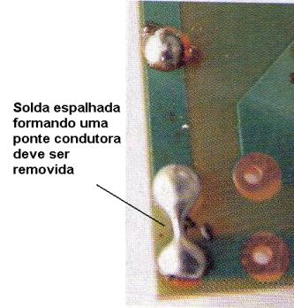
The weld can spread and connect two terminals of the same component or other components that are near as shown in Figure 7. Unmake this union using the welder.
c) Resistor value exchange
The resistors must be in the right positions. Check out their placement by the colors of the rings. By positions we understand the values ??given by the colors.
d) Wrong capacitors values
The capacitors are also commonly exchanged, especially between 4.7 pF and 47 nF. Make sure each one is in the right place. These capacitors must also be of ceramic disc. If other types are used, the transmitter will not work.
e) Transistor inversion
The position of the transistor must be observed. The flat side is the reference. If it is reversed the device will not work.
f) Battery holder Inversion
The wire colors identify the positive and negative poles. See if they were not reversed.
g) Electret microphone Inversion
The electret microphone has two terminals. One is connected to the frame by a small extension. This is the negative terminal. If there is an inversion the transmitter sends the signal (a signal it captured) but the voice is not played
Semiconductors:
Q1 - BF494 or BF495 - RF transistor NPN
Resistors: (1/8 W, 5%)
R1 - 5.6 k Ω - green, blue, red
R2 - 10 k Ω - brown, black, orange
R3 - 8.2 k Ω - gray, red, red
R4 - 47 Ω - yellow, violet, black
Capacitors:
C1 - 10 µF / 12 V - electrolytic
C2 - 4.7 nF (4700 pF or 472) - ceramic
C3 - 4.7 pF (4.7 or 4J7) - ceramic
C4 - 100 nF (104 or 0.1 µF) - ceramic
Miscellaneous:
CV - trimmer
L1 - antenna coil
MIC - electret microphone
A - piece of wire of 10 to 15 cm - antenna
Printed circuit board, battery holder, etc.


