A coveted device by detectives, spies and even curious ordinary people, is the microphone that lets you hear "through walls". Of course, such a device is still in the field of fiction, although there are some interesting alternatives that have already begun being researched or that make use of very advanced technologies, beyond the reach of a common assembler.
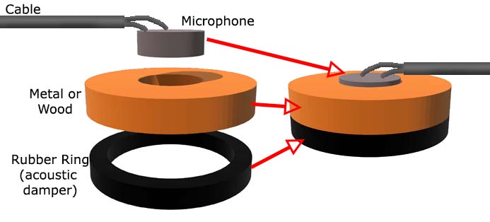
So what we propose is an ultra-sensitive microphone that detects very faint sounds that can pass through a wall and captured if we use an appropriate sensor configuration. What we have then is a ultra-high gain amplifier with a common microphone placed in a sound concentrator pad system, as shown in figure 1.
Microphones of this type have been used by water supply companies to detect hidden leaks by the sound they produce, as shown in Figure 2.
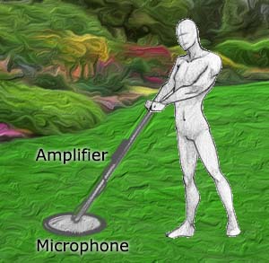
Water supply companies then send their technicians with such a device, usually at night when there is less environment noise, to try to find those impossible leaks which make a water bill reaches absurd values ??and there is no obvious sign of what is happening... See then that our device does not have only a recreational purpose since it can be used to:
Detect leaks
Detect unusual noises occurring due to animals or insects housed in buildings (walls, ceilings, etc).
Detect noise caused by malfunctions in machines
Detect crackles and changes in the position of beams and walls when subjected the efforts to see if they have any crack or another problem.
Detect objects within suspicious packages or bags indicating a mechanical artifact - a time bomb, for example.
The proposed circuit is powered by standard batteries and has a relatively low consumption, which makes it completely portable.
How it Works
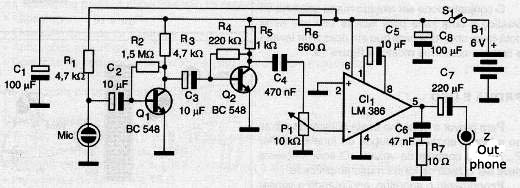
An electret microphone sends its signal to a pre-amplifier stage audio with a very high gain. This stage is formed by the transistors Q1 and Q2 whose gain is basically given by the relationship between the collector and the base polarization resistors. This stage is the kind of RC coupling for greater design simplicity.
The signal of this stage is taken to the input of a 200 gain integrated amplifier, which is determined by the capacitor C5. See that in the passage of the signal from one stage to the other we have the P1 sensitivity control potentiometer.
The amplified signal by the integrated circuit is led to a headset where it is then made its reproduction. For the circuit provides satisfactory results there are two important conditions that must be satisfied in the assembly.
The first is the use of a captured pad where the microphone is installed in a way to focus only on the sound coming through the wall. Constructive details about this sensor pad will be given later.
The second is the use of a padded headset with low impedance. This type of headset, shown in Figure 3 has two purposes in this project.
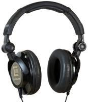
The first consists on the greatest concentration of the sounds in the ear of the person using the device, obtaining thus higher performance. The second consists on avoiding the phenomenon of acoustic feedback or howling, illustrated in Figure 4.
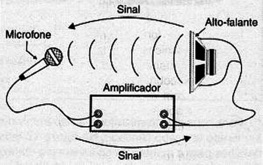
When the microphone of a sound equipment captures the very sound it reproduces the signal circulates quickly through the circuit, producing an intense whistle. It is the whistle that occurs when we open the volume of a sound equipment where a microphone is connected. Using a padded handset we avoid this problem, since the circuit is very sensitive. The unit's power comes from 4 ordinary batteries and because the consumption is not the highest they have a good durability
Assembly
In Figure 5 we have the device complete diagram to "Hear Through Walls".
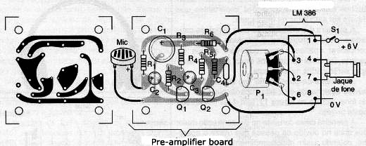
The printed circuit board for its implementation is shown in Figure 6.
For the microphone connection to the device, should be used a shielded cable. In Figure 7 we show details for the assembly of the sensor and the cable connection, observing the polarity of the microphone
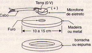
The cable can have up to 3 meters in length to facilitate its use.
The electrolytic capacitors must have their polarity observed. For the phone connection must be used a jack according to its plug. Like most headphones of low impedance padded type is stereo and the amplifier we use mono, we need to make the connection of the two channels in series, which is achieved in the jack itself, as shown in Figure 8.

Without this connection only one channel works. The set can be housed in a plastic box and an idea to facilitate its use would be to provide it with a handle so it can be taken over the shoulders, as shown in Figure 9.

Test and Use
To test the device, we just need put the batteries in the holder, attach the headset plug and trigger P1. Open the volume control. The ambient sound should be heard in a much more amplified way. Test the device touching the sensor on a wall where there are people talking on the other side or making some kind of noise. To use we just touch the sensor on the wall, looking for the position to give a better performance. If you hear a loud whistle due to feedback, lower the volume.
Semiconductors:
CI-1 - LM386 - integrated audio amplifier
Q1, Q2 - BC548 or equivalent – General purpose NPN transistors
Resistors (1 / 8W, 5%)
R1, R3 - 4.7 k Ω - yellow, violet, red
R2 - 1.5M Ω - brown, green,
R4 - 220 k Ω - red, red, yellow
R5 - 1 k Ω - brown, black, red
R6 - 560 Ω - green, blue, brown
R7 - 10 Ω - brown, black, black
Capacitors: (Electrolytic 6 V or more)
C1, C8 - 100 µF - Electrolytic
C2, C3, C5 - 10 µF - Electrolytic
C4 - 470 nF - ceramic or polyester
C6 - 47 nF - ceramic or polyester
C7 - 220 µF - Electrolytic
P1 - 10 k Ω - potentiometer (can include S1)
Miscellaneous:
MIC - two-terminal electret microphone
S1 - Single switch
B1 - 4 small batteries
Z - Low impedance Phone - see text (4-32 Ω)
printed circuit board, jack for headphone (stereo), battery holder, mounting box, button to pot, wires, welding, etc.


