This project produces a handy tool for audio (and RF) troubleshooting.
The described audio generator produces squarewave signals between 100 and 1,000 Hz but can easily modified to operate in a wide range with some changes in the original circuit.
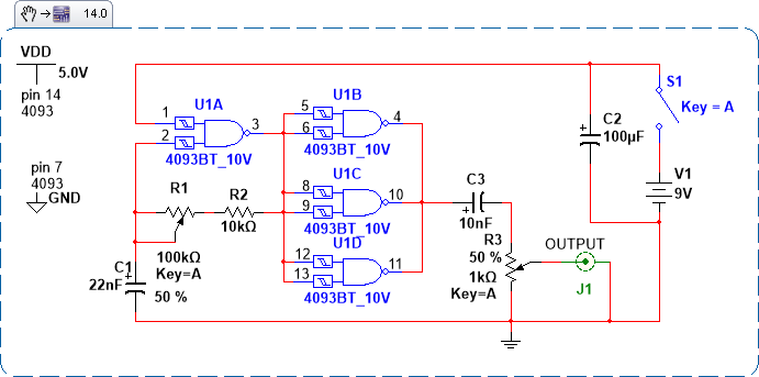
The output signal voltage can be adjusted from 0 V up to the power supply voltage, in a range up to 9 V. A complete diagram of the audio generator is shown in Fig. 1.

C1 and R1 determine the frequency range of the audio generator.
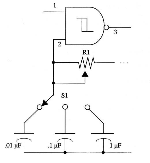
C1 can be altered to other frequency ranges, but the best way to get a large-band audio generator is to connect a band switch with two or more capacitors as shown in Fig. 2.

Using capacitors with values suggested in this circuit, you can generate square signals up to 100 kHz.
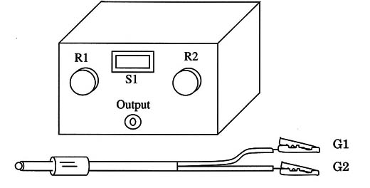
All the components can be housed in a small plastic box as shown in Fig. 3.

Frequency is adjusted by R1, and the amplitude is adjusted by R3.
Audio Generator
IC1 - 4093 CMOS integrated circuit
R1 - 100,000 Ω - linear potentiometer
R2 - 10,000 Ω, 1/4 W, 5% resistor
R3 - 1,000 Ω - linear potentiometer
C1 - 0.022 µF - ceramic or metal film capacitor
C2 - 100 µF, 12 WVDC electrolytic capacitor
C3 - 0.01 pF ceramic or metal film capacitor
S1 - SPST switch
B1 - 6 V (four AA cells) or 9 V (battery)


