This operation must be done with caution to avoid contact with conductors carrying the high voltage.
You can use the device in experiments with high-voltage generators and many other applications at home and in school scientific projects and experiments.
The circuit is portable and it is powered from four AA cells or a 9 V battery.
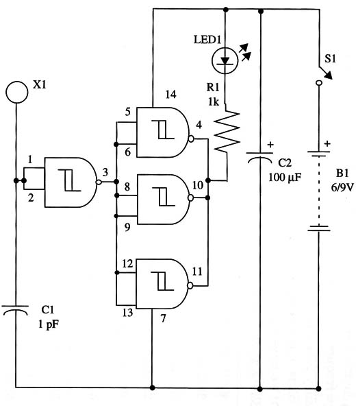
The presence of static charges or electric high-voltage fields is indicated by an LED.
A schematic diagram of the electroscope is shown in Fig. 1.

The sensor is a small wire ring. The circuit can be housed into a small plastic box.
Capacitor C1 can be a “home-made” unit.
You just have to twist two 2-inch solid wire pieces to form a capacitor.
To operate, bring a charged source close to the sensor. A piece of paper stroked with a rod if insulating material will do.
The LED will glow according the charge movement.
IC1 - 4093 CMOS integrated circuit
LED1 - Red common LED
S1- SPST slide or toggle switch
B1 - 6 V or 9 V (four AA cells or 9 V battery)
X1 - Sensor (see text)
C1 - 1 pF ceramic capacitor
C2 - 100 µF, 12 WVDC electrolytic capacitor
R1 - 1,000 Ω, 1/4 W, 5% resistor


