The TPS (Transformerless Power Supplies) are ideal for applications where the power grid isolation is not a major factor in the design. This will occur in cases where the device is completely enclosed in a box of insulation material without the danger of direct contact with any energized part.
These sources are also interesting for the case of powering low consumption appliances, where the alternative components, as we will see, are small and cheap. For applications where consumption is high, the technology does not apply simply. The alternative components in this case can be large and heavy and in addition, a very important additional factor that is safety matters.
A conventional source
In a conventional analogue source, what we have is a transformer that lowers the voltage of the power grid and acts as an insulation element, as shown in Figure 1.
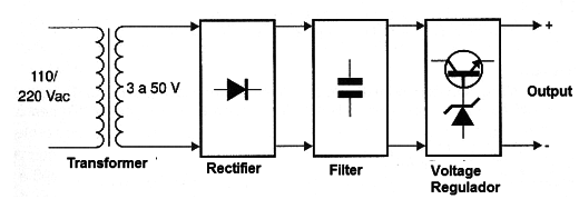
After this transformer we have the stages of rectification and filtering, eventually followed by a voltage regulator circuit. The basic problem with this architecture is in the transformer which is a heavy and expensive component.
The higher and heavier the transformer, the higher the power demanded by the supply circuit, ie the product of the voltage by the current. In Figure 2 we have some examples of transformers normally used in supplying circuits from 5 to 30 V with currents in the range from 50 mA to 10 A.
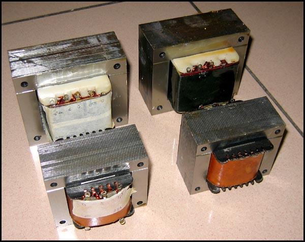
These transformers are formed by heavy rolled iron cores around which the coils forming the primary and the secondary are wound.
How to Replace the Transformer?
An initial idea is to make a resistive divider, so that the voltage of the grid is lowered and after that can be rectified and filtered, as shown in Figure 3.
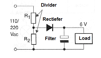
However, this configuration has several serious problems. The first one is that the resistor R1, usually because it is much larger than R2, depending on the current demanded by the load, must have a very high dissipation.
Even for a source of a few tens of milliamperes, powered in a 110/220 V grid, this resistor must have several watts of dissipation. In addition to the size it represents, we have the additional problem of heating and wasting energy, which is unacceptable nowadays.
The other problem is more serious. The voltage in the divider does not only depend on the value ratio between the resistors that form it, but also on the load consumption. Thus, when the load is connected, it represents the connection of an additional resistor in parallel that consumes energy and, therefore, causes the voltage to drop, as shown in Figure 4.
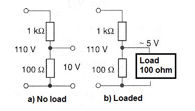
Such a source must then be designed to have a much higher voltage and with the load powered, dropping to the desired value.
A zener diode or a regulator circuit is therefore fundamental for this type of configuration.
Using Capacitors
An interesting alternative for the use of R1 in a transformerless source is to take advantage of the capacitive reactance of a capacitor. A capacitor has an impedance (measured in Ω) which depends on its value and the frequency of the signal being applied to it.
We can say in a simpler way that a capacitor behaves like a "resistor to alternate the current", as shown in Figure 5.
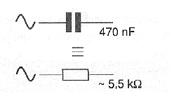
This impedance can be easily calculated by the formula;
Zc = 2 x π x f x C
where:
Zc is the reactance presented by the capacitor in Ω
π = constant = 3.14
f is the frequency of the current in hertz
C is the capacitance of the capacitor in farads
See then that we can connect a capacitor in series with a resistor so as to obtain a voltage divider that will operate normally with alternating voltages.
What is the advantage of this configuration?
The first is in the fact that the capacitor does not dissipate power in the form of heat when it operates in this divider. It operates by loading and unloading therefore having no resistive elements to generate heat.
In other words, there is no loss of energy in this component, which means that besides not being wasteful it does not work when it is hot. In practice, there is a small loss, because no capacitor is perfect, but it is very small. The disadvantages exist of course. One is in the fact that the capacitor must be larger the higher the current desired to feed the load. The current depends on the reactance in an inverse ratio.
The higher the current, the lower the reactance and the lower the reactance it implies on a greater capacitance.
The other disadvantage lies in the fact that the capacitors for this application need to have high insulation voltages and this means special construction capacitors, and the more expensive the higher their capacitance. These factors limit the use of this architecture to small sources that should not provide more than 100 mA under voltages in the range of a few volts up to about 30 or 40 V.
The configuration
A basic configuration for such a source is then shown in Figure 6.
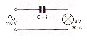
From it, we will teach the reader to calculate the components that must be used and come up with a practical project. For this let’s suppose we wish to feed a small 6 V lamp with a current of 20 mA. Our first step consists in calculating which is the reactance that the capacitor must present to form a divisor as shown in Figure 7.
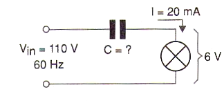
In this problem we have:
V = 6 V
Vin = 110 V
I = 0,02 A (20 mA)
F = 60 Hz
C = ?
We start by determining which is the resistance that the load (lamp) has when fed by a voltage of 6 V and covered by a current of 20 mA.
R = V/I
V = 6 V
I = 0,02 A (20 mA)
R = 6/0,02
R = 300 Ω
Next, we determine the impedance that the whole circuit should have when supplying 0.02 A at 110 V:
Z = 110/0,02
Z = 5 500 Ω
From there on we can calculate the capacitive reactance that the circuit must present, which is given by the following formula and calculations:
The capacitive reactance of the capacitor should be 5 500 Ω. In the 110 V x 60 Hz grid, it corresponds to a capacitor of:
A capacitor of 470 nF will meet our needs. The peak voltage in the 110 V grid is:
Vp = 110 x 1,41 = 155,1 V
This means that a polyester capacitor with at least 200 V of working voltage must be used. Since the voltage in this type of divider varies according to the current in the load, we can add a regulating stage using a zener diode.
The voltage will be of 6 V and the dissipation will be given by the maximum current flowing through the regulator circuit when in the absence of load, in the order of 0.02 to (20 mA). In Figure 8 we show how to add this diode.
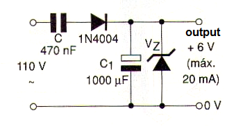
Thus, in this condition, the power dissipated in the diode will be:
By giving a tolerance, so that the diode does not overheat, when there is no load to be fed, we can use a type of 400 mW or even 500 mW.
Conclusion
Transformerless power supplies are an excellent alternative for powering low consumption appliances from the power grid. However, you must be very careful with its insulation, as the powered device will be connected directly to the grid. Likewise, capacitor limitations prevent this type of source from being used at power devices that typically consume more than 100 mA.


