Translated into English by Patricia Lima Carlos.
Many common bodies can function as detectors of high frequency signals, i.e., radio wave detectors picked up by an antenna.
It is even well known the story of a dental prosthesis that, picking up signals from a nearby station, caused its bearer to "hear things" directly through the tooth without the need for a radio, and this "listener" was taken to several psychiatrists before discovering the origin of the phenomenon. In the story "Dental Interface" our character Prof. Ventura, with his students Bart and Bert, are involved in an adventure in which this whole phenomenon is detailed.
Note: The story is available in the adventures section of Prof. Ventura on this site.
The radio we propose in this article also uses unusual means of detecting signals: a razor blade (used or new). If you like new experiences with electronic technology, this is very interesting.
The Basics
Two metals or bodies of different natures, when in contact, may have properties similar to those of the semiconductor diodes and thus detect radio signals. The traditional "cat whisker" on a galena crystal is undoubtedly the oldest experimental type of detector and therefore known to those who study the radio history. The first radios that existed, the so-called "galena radios", had as detectors the configuration shown in Figure 1.

By touching a sensitive point on the crystal, the mustache formed a semiconductor contact capable of rectifying the tenuous high-frequency currents induced in the antenna by the radio signal. The result was the detection for later filtering and application to a headset, where they resulted in sounds.
Since there was no amplification at that time (the transistors and valves had not yet been invented), the signals had the power that the antenna could capture, which required that it had large dimensions. Our radio uses a different detector.
Experimenting with several combinations of bodies we got many that gave satisfactory results, such as a steel straw, a piece of graphite on an aluminum plate. But what we propose can undoubtedly be the basis of this project that would make huge success in a fair or demonstration for your curiosity: it uses an unusual detector and does not need transistors or valves.
How it works
The basic structure of our radio is shown in Figure 2.

The tuning and antenna stage has the function of capturing the signals from the stations and separating the one from the one we wish to hear. Since the radio does not have amplification, the antenna should be as long as possible to capture the maximum power of the station (which must be strong and close enough).
An antenna for this radio should be a wire stretched at least 10 meters in length. The tuning circuit has a variable capacitor and a coil, as shown in Figure 3.

The signal from the tuning circuit is taken to the basic element of the design which is the detector. This detector, which should work as a common diode (nothing prevents a diode 1N34 or equivalent to be used to obtain a common crystal radius), consists of a razor blade and a piece of graphite taken from a black pencil.
The sensitive touch of the graphite on the blade, at points to be obtained experimentally, makes the set function as a detector of high frequency signals induced by radio waves.
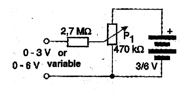
This detector is able to separate from the high frequency signal coming from the tuning circuit the low frequency signal corresponding to the sounds. These sounds, in fact, low frequency currents, are taken to the next stage which is a headset. In the circuit, there is also a polarization network formed by a potentiometer and a resistor, as well as a 6 V alkaline battery (4 cells) as shown in Figure 4.

The purpose of this network is to "polarize" the detector, helping it to stay close to the ideal conduction point for detection to occur. This happens because the signal coming from the antenna, which is very weak, must only be added to the available voltage so as to exceed the point where the detector is conducting.
Components
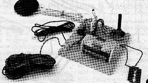
As it is an experimental radio, a lot can be improvised and even taken advantage of out of use electronic devices. Some components only need to be purchased from specialist stores. We suggest that the assembly is made based on a wooden or plastic board, as shown in Figure 5.

The coil L1 is wound on a ferrite rod of any diameter for about 1 cm, being formed by 80 to 100 turns of enameled wire of 26 to 30 AWG or even wired wire 22. This coil will be attached to the assembly base through two clamps.
The variable capacitor may be of the miniature or large type drawn from some old disused radio. If you have more than one section we use only one of them keeping the other one off. The headset must be of the piezoelectric type or crystal of high impedance, since other types have no sensitivity, mainly the low impedance ones found in walkmans and CD players.
A phone capsule can be experimented. The capacitor C1 is ceramic, from 47 pF to 120 pF, and the resistor is 2.7 M Ω or so. The potentiometer is 470 k Ω at 1 MΩ. The battery will be formed by 4 small alkaline batteries, which will have an enormous durability given the low consumption of the device. These batteries should be built in a suitable holder.
The most important is the assembly of the razor detector which is made as shown in Figure 6.

This detector is formed by carefully attaching a wire to a piece of graphite which will form the anode of the diode 2, and carefully connecting the other wire to a common razor, forming the cathode of the diode 1.
The graphite should simply be supported on the razor and possibly its position changed a few times until the one that results in greater sensitivity is achieved. For the connection of the antenna and ground, common terminals or a terminal socket with screws are used.
Assembly
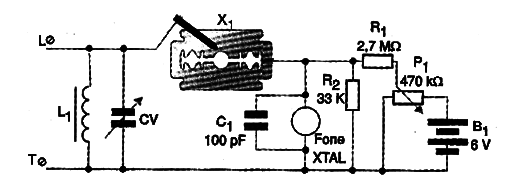
The welding of the components should be done with a small power iron of fine tip. All connections except the graphite and razor should be welded. In Figure 7 we have the complete diagram of the radio.

In Figure 8 we give an idea of ??the real arrangement of the components with their connections, remembering that everything must be fixed in the wooden base.

For the assembly to come out perfectly, observe the following points:
a) Thoroughly scrape the ends of the L1 coil wires before welding them.
b) When welding the variable, carefully observe the arrangement of its terminals and use a plastic button to facilitate the tuning.
c) Quickly weld the capacitor C1 and resistor R1 so that the excess heat does not damage them.
d) Connect the potentiometer according to the drawing, and the wires of the battery holder observing its polarity. The red wire is positive (+) and black one is negative (-).
e) Complete the assembly by welding the detector wires.
Then check the assembly and the radio operation.
Test and Use
First of all, provide a good antenna and a ground connection. The antenna, as shown in Figure 9, may be attached by its ends in insulators.

Two trees, masts or other objects can serve to hold the antenna which should be as large as possible. The longer the antenna, the better the signal strength obtained. Grounding can be done on any large metal object that is in contact with the ground, such as a water pipe, aluminum door or window frame, etc.
Once the antenna and ground are connected to the radio, place the handset close to the ear and support the graphite on the razor. Adjust at the same time, very carefully the tuning and P1, until you pick up some station. If nothing happens other than clicking, look for a new position of the graphite on the razor until you get satisfactory results.
The volume, like all the radio without amplification components, will be very small, but the sound quality will be clear. Remember that at the beginning of the last century radio receivers had this same principle of operation and sound quality.
In the technological educational classes, encourage the research on the primitive times of the radio applying the program STEM:. Suggest names search as:
Marconi
Brandt
Coherer
X1 - razor detector - see text
XTAL - Crystal phone - see text
L1 - Antenna coil - see text
CV - Variable capacitor from 120 to 410 pF
C1 - 100 pF - ceramic capacitor
R1 - 2.7 M Ω - resistor - red, violet, green
P1 - 470 k Ω - potentiometer
B1 - 6 V - 4 small alkaline batteries
Miscellaneous:
A base for the assembly, terminal bridges, battery holder, long antenna, enameled wires, ferrite rod, razor, piece of graphite, common wires, welding, etc.


