"Galena" or "crystal" type receivers are characterized by not having amplification stages: any signal that is obtained on the headset depends on the radio signal which is picked up by the antenna. Thus, the efficiency of this type of radio directly depends on the efficiency and proximity of the antenna.
How can we do to capture the weakest radio stations?
The advent of the transistor made possible the amplification of the signals, but the transistors need energy and this can have diverse sources, such as alkaline batteries and, more curiously, solar cells, experimental generators, etc., which we have already described in many articles.
One source of energy we have not exploited is the one which comes from space itself and which consists of the signals from the strongest stations.
Thus, we can use the signal from a strong station to power a transistor, which will amplify the signals from the weakest stations!
Our experimental design can be implemented with one or two antennas and can serve as a starting point for interesting discoveries.
HOW IT WORKS
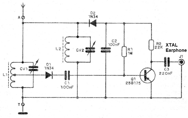
What we do is to have, from one or two antennas, two signals: one which corresponds to the strongest station and is selected in L2 and CV2, obtaining a very small voltage that, filtered by C2, feeds the transistor Q1 which functions as an amplifier; the other, corresponding to the station we wish to listen to, is detected by D1 after tuning in CV1 and L1 and taken to the input of the transistor where it is amplified.
Since the voltage obtained from detection by D2 and filtered by C2 is very low, we can only have some success with this type of circuit if the transistor is germanium. We use the 2SB175, but equivalents, like the 2SB54, can be experimented.
The headset must also be very sensitive, giving preference to the crystal types, since others, such as those of low impedance found in walkman and even in some radios, will not be driven, and therefore there will be no sound.
The antenna must be very long, at least 10-meter long, and the earth connection must be very efficient, it can be the neutral pole of the socket or any object of bearing in contact with the ground.
ASSEMBLY
In Figure 1 we give the complete diagram of our radio.

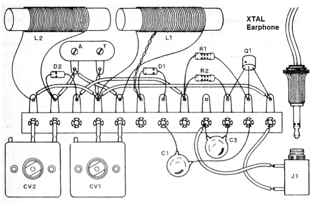
The assembly, which can be carried out on a terminal strip, is shown in Figure 2.

The coils are the same except for the plug, consisting of 80 to 100 turns of 28 or thicker enamelled wire. The L1 socket is made on the 40th turn.
The variable is of a section, and can be taken advantage of wave radios, averages with capacitance between 175 and 410 pF.
The diodes must be germanium, such as 1N34, 1N54, 1N60, etc. Silicon types, such as 1N4148 or 1N914, should not be used.
The capacitors are ceramic or polyester and the resistors are 1/8 W.
For the transistor it is important to note 3 connection positions: the collector is identified by a pint or triangular mark.
The Test and use
Connect the unit to a good external antenna (or two, one for L1 / CV1 and one for L2 / CV2).
Tune to a station first on CV1 and then set CV2 for higher volume. This greater volume comes precisely from the amplification of the transistor, which occurs with the signal reception by CV2 and L2.
Q1 - 2SB75 or 2SB175 - PNP germanium transistor
D1, D2 - 1N34 or 1N60 - germanium diodes
L1, L2 - antenna coils - see text
CV1, CV2 - variables for medium waves
C1, C2 - 10onF - ceramic or polyester capacitors
C3 - 220 nF or 330 nF - ceramic or polyester capacitor
R1 - 1 M at 2M2 - resistor
R2 - 22k at 47k - resistor
J1 - jack for headset connection
Miscellaneous: ferrite sticks, crystal earphone, wires, welder, antenna, terminal bridge, etc


