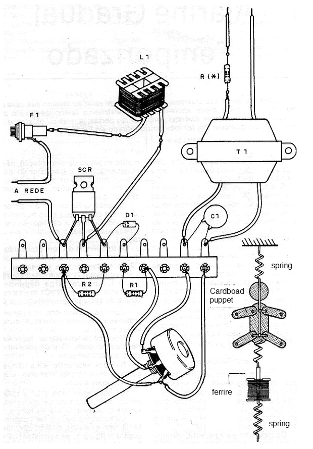
The basis of this circuit is a silicon controlled diode (SCR) that drives a reel harnessed from a small unused transformer. The magnetic field created inside this coil attracts an iron core or ferrite which then moves causing a small puppet to dance. The articulated doll is held by a spring and admits many mounting possibilities.
The core of the coil may be a small ferrite rod or even a screw of at least ½ inch (1.2 cm) in diameter that can move freely within the coil L1.
This coil is the primary winding of a small 110 V or 220 V transformer with any secondary 200 to 500 mA. The coil core is carefully removed, leaving only the spool exposed.
The transformer T1 may be of any type with a primary of 110 V or 220 V and a secondary of 6 to 12 V with a current in the range of 250 to 500 mA. This component is not critical as it serves only for insulation to the sound signals of the amplifier in relation to the high voltage trip circuit.
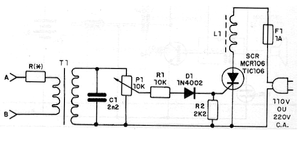
The adjustment of the sensitivity and the point of operation is done in P1. This setting depends on the power and volume of the stereo. The resistor R must be chosen according to the power of the sound device, as shown in the table below. The A and B wires are connected to the sound output of the unit in parallel with the loudspeaker. Note that the used L1 wires are those that correspond to the primary winding (black and red or black and brown).
Amplifier Power = R (ohms)
0.5 to 5 W = 10
5 to 25 W = 47
25 to 50 W = 100
50 to 100 W = 220
Above 100 W = 470
The resistor must be a common 1 W type.
Assembly
In figure 1 we have the complete diagram of the mobile.

As it is a beginner assembly, we suggest the use of a terminal bridge, as shown in figure 2. The most advanced readers can assemble based on a printed circuit board.

We note that this is a circuit powered by the power grid. For this reason, its parts should not be exposed as they could cause dangerous shocks. On the other hand, the connection to the output of the stereo is isolated by T1, so there is no danger of shock or short at this point.
Adjustment and Use
To use connect the input in parallel with the sound output of the stereo (speaker wire) or handset jack. Place the stereo at medium volume and adjust P1 so that the puppet moves by the pulling force of the nucleus. Position doll and spring for best performance.
We note that if the system is turned on at the handset output, the sound from the speaker will be cut off, so a small speaker must be connected in parallel to accompany playback.
SCR – TIC106 oe MCR106
D1 – 1N4002 or 1N4004
P1 – 10 k ohm – potentiometer
L1 – see text
C1 – 2n2 – ceramic or poliester
R1 - 10 k ohm x 1/8 W
R2 – 2k2 ohm x 1/8 W
F1 – 1 A
Other: terminal strip, wires, transformer, ferrite rod or screw, etc.


