With the used SCR loads of up to 400 watts in the 110 V grid and 800 W in the 220 V grid can be controlled by an audio signal just as in the previous version (ART350E project).
Small FM radios can be used as remote control receivers in this interesting tone trigger.
THE PROJECT
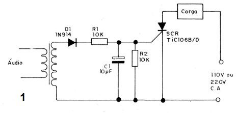
The audio signal taken from the handset or speaker output of the receiver and applied to the driver by means of an isolation transformer; which guarantees complete operation safety,
This signal is rectified by D1 and then filtered by R1 and C1, and then applied to the gate of the SCR, where the trigger occurs,
With the trigger, the SCR conducts the current and triggers the load on the power grid.
Note that the load only remains on while the transmitter's audio tone is present.
Any of the tone modulated transmitters we describe can operate with this circuit connected at the output of a receiver, including those described in previous designs.
ASSEMBLY
In figure 1 we have the schematic diagram of the high power tone control.

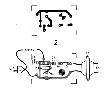
Figure 2 gives a suggestion of arrangement of the components on a printed circuit board.

The SCR must have a heat radiator and the anode and cathode tracks of this component should be thicker.
The transformer can either be of the type used in older transistor radios outputs or even a 110 V / 6 V transformer where the 6 V winding is connected to the audio output of the receiver.
The electrolytic is for 12 V and the resistors are 1/8 W. The sensitivity of the circuit and controlled in the receiver's own volume control.
PROOF AND USE
The procedure for adjustment and use is exactly the same as for project ART350E.
Checking the perfect functioning of the unit is only to proceed with its installation in order to control, remembering that this circuit is not suitable for motors, fluorescent lamps or electronic devices, but only for lamps, heaters and other resistive loads.
SEMICONDUCTORS
SCR - TIC106B (110 V) - TIC106D (220 V) - Silicon Controlled Diode
D1 - 1N914 - silicon diode
RESISTORS
R1 and R2 - 10 k ohm (brown, black, orange)
CAPACITORS
C1 - 10 uF (electrolytic)
VARIOUS
T1 - Transformer - see text
Printed circuit board, power cable, wires, solder, etc.


