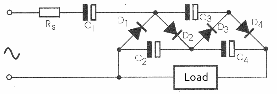
There are several practical solutions to obtain a continuous voltage greater than the peak value of an alternating voltage from a rectification and filtering process. In fact, we can multiply alternating voltages, obtaining continuous voltages of much higher values using only passive components such as diodes and capacitors. Doublers, triplers or even multiplier configurations by any positive integer factor are quite common in power supplies for many electronic devices. For the reader who wishes to make use of these configurations, we give some of them below. Note that these circuits are basically designed to operate on the 60 Hz network, however, they can also operate at higher frequencies, in which case the capacitors can have their values reduced proportionally.
1. Conventional voltage doubler
This configuration is shown in Figure 1, using two diodes and two capacitors.
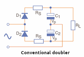
The working voltages of the capacitors must be at least the peak value of the input voltage. The values of Rs and Rc are quite low, normally serving to limit current surges when the circuit is turned on, finding the capacitors discharged. Too much current at this point could damage the diodes. Typical values for mains voltage are 10 to 50 µF for capacitors. The diodes can be 1N4004 for the 110 V network and 1N4007 for the 220 V network, up to about 500 mA output, typically.
2. Cascade voltage doubler
This configuration is shown in Figure 2 and uses two diodes and two capacitors.
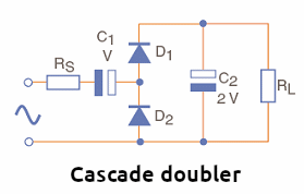
Capacitor C2 in this configuration, however, must have a working voltage that is twice the peak input voltage. The purpose of Rs in this circuit is the same as in the previous circuit. Typical values for diodes and capacitors are the same as in the previous circuit.
3. Bridge voltage doubler
This configuration works in full wave and uses four bridge diodes. We show its circuit in figure 3. The output voltage will be approximately double the input voltage.
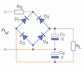
Note that both capacitors must have working voltages that are at least the same value as the peak input voltage. It is also convenient to use a resistor Rs at the input to avoid high voltage spikes in the circuit when the source is turned on.
4. Full-wave voltage tripler
The output voltage of the circuit in Figure 4 is approximately three times the input voltage.
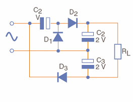
Three diodes and three capacitors are used, with the minimum working voltages of the capacitors being at least 50% higher than the peak input voltage. Vm in this circuit is the average value of the input voltage. A resistor (Rs) can be added in series with the input as in the previous circuits, to limit the current at the moment the source is turned on.
5. Cascade voltage tripler
The circuit in Figure 5 provides a voltage at its output that is approximately three times the input voltage.
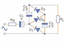
The minimum working voltages of capacitors are at least 50% higher than the input peak. The resistor Rs limits the current at the moment the circuit is turned on and finds the capacitors
6. Full-wave voltage quadrupler
The circuit shown in Figure 6 provides at its output a voltage approximately 4 times greater than the voltage applied at its input discharged.

The values of the minimum working voltages of the capacitors are indicated in the diagram itself. Again, the voltages of the capacitors must be greater than the input peak. It is also recommended to use a resistor (Rs) in series with the input.
7. Half-wave voltage quadrupler
This circuit uses four diodes and four capacitors multiplying the input voltage by 4. The values of the minimum working voltages of the capacitors are greater than the input peak as in the other circuits. Figure 7 shows the complete quadrupler circuit.
8. Voltage multiplier by n
In the circuit in Figure 8, n can be any positive integer factor, and the input voltage will be multiplied by it.

Capacitors used in this circuit must have minimum voltages greater than the input peak. We remind readers that we cannot create energy. Thus, as we obtain higher voltages with the multiplication given by these circuits, the currents available in the load become proportionally smaller. It should also be taken into account that in the voltage multiplication process there are losses to be considered, which further reduces the current that we can obtain at the outputs and consequently the power.

