Magnetic pickups for guitars and guitars are low impedance devices that provide a low-intensity signal, on the order of a few millivolts, insufficient to excite common amplifiers whose sensitivity requires at least a few hundred millivolts to operate at full power.
This means that if we connect ordinary pickups directly to commercial amplifier inputs (from stereo, 3-in-1 etc.), we will not even get a volume comparable to that of the instrument itself without any recourse.
To properly excite such amplifiers and with that we can connect guitars and guitars, it is necessary to use a preamplifier with its own characteristics.
This preamplifier must be specific for low impedance input and must operate on batteries for greater versatility of use. It is precisely this project that we are proposing in this article.
With it, even a homemade pickup can excite an ordinary amplifier.
Characteristics
Input sensitivity: 5 to 10mV
Output signal: 500 mV
Input power: less than 10 ohms
Supply voltage: 6 V
Voltage Gain: 100
How it works
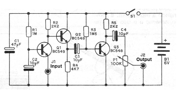
Three transistors are used in a normal configuration amplifier circuit.
The first transistor operates on the common base configuration, so that we have a low input impedance. For this function the option is a BC549 which, in addition to an excellent gain, is characterized by its low noise level.
The other transistors operate in the common emitter configuration and in the output we have a potentiometer that allows to dose the intensity of the output signal so that there is no saturation of the amplifier used.
Assembly
In figure 1 we have the complete diagram of the apparatus.
In figure 2 our suggestion of printed circuit board.
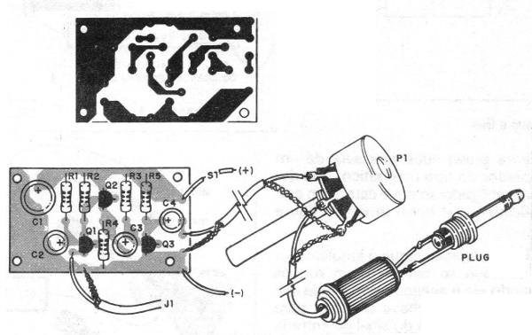
As this is a very sensitive preamplifier, the primary concern that the assembler must have is with regard to tinnitus pickup.
Thus, we suggest the use of a metal box with the battery negative connected to it, so that it serves as a shield.
The connection cable to the potentiometer and the input jack must be shielded, the same as for the output cable.
With respect to the components used are the following the main recommendations:
a) Q1 must be BC239 or BC549 at its lowest noise level. The others may be BC547, BC548, BC549, BC237, BC238 or BC239. Observe their mounting positions.
b) The potentiometer is simple, linear, possibly with the general key S1.
c) The resistors are all 1/8 or ¼ W and their values are not critical.
d) The capacitors are all electrolytic with working voltage from 6 V. Note their polarity in the connection.
e) The input jack must be in accordance with the one used on the pickup, and for the output we can use a jack connecting an extension cord or leave a shielded wire with a plug in the tip, this according to the input of your amplifier ( auxiliary input or AUX).
f) The battery consists of 4 small batteries, which need a suitable holder. Observe the polarity of these batteries by the color of the wires in the holder. The red corresponds to the positive pole.
Upon completion of the assembly, the operating test and use are immediate.
Test and Use
For proof you will need a magnetic type pickup, which should be connected to the pre and this to an amplifier as shown in figure 3.
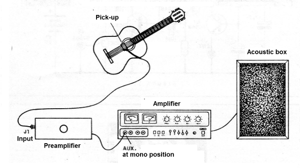
Once the connection is made, turn on the amplifier and check that no snoring occurs when it is adjusted to 3/4 of its volume with the selector switch to allow input from the auxiliary input signal.
Realize that there is no snoring, call S1. If there is snoring, check the input and output wire shields.
Then set P1 to best playback.
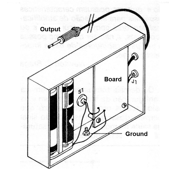
To use the device, install it permanently in its box, as shown in figure 4.
If you operate on a set and you have to connect more than one of these preamplifiers to the same amplifier, you must do as shown in figure 5.
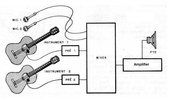
The pre-instrument must be connected to a Mixer.
Q1 - BC549 or equivalent - NPN transistor
Q2, Q3 - BC548 or equivalent - NPN transistors
P1 - 100 k - potentiometer with or without key
R1 - 1 M x 1/8 W - resistor (brown, black, green)
R2 - 2k2 x 1/8 W - resistor (red, red, red)
R3 - 1M5 x 1/8 W - resistor (brown, red, green)
R4 - 4k7 x 1/8 W - resistor (yellow, violet, red)
R5 - 2k2 x 1/8 W - resistor (red, red, red)
C1 - 47 uF - electrolytic capacitor
C2, C3, C4-10 UF - electrolytic capacitor
S1 – On-Off switch
B1 - 6 V - 4 small batteries
Miscellaneous: box for mounting, shielded wires, printed circuit board, support for 4 batteries, knob for potentiometer, input jacks and output plug, wires etc.


