Without potentiometers or other control devices in the output, this source maintains its voltage as a function of the load of a capacitor.
As the current that the FET operational amplifier requires to take this reference voltage is extremely low because its input resistance is 1012 ohm, the capacitor holds for hours at the same voltage that is fixed by the touch of its fingers.
It is a source, obviously experimental, because to power circuits where high voltage stability is required, the system is useless.
Using a 12 V x 1 A transformer we can get output voltages of just over 12 V, but nothing prevents a 15 V transformer and even 20 V is used to achieve a higher output voltage at the limit.
Even the integrated CA3140 can be used in this version as well, as it is an operational amplifier with FET at the input. (figure 1)
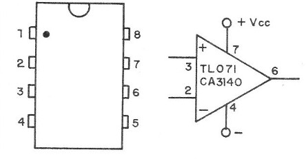
The circuit
The basic idea is simple: an operational controlling the output voltage via two transistors, one being power.
In this case, however, as the operational amplifier has a very high input resistance, we can use for reference not a zener diode, as usual, but a capacitor loaded with the desired voltage at the output.
The very high operational input resistance prevents the load from flowing, thus changing the output voltage in short periods.
What usually occurs is the loss of this load by leaks or by the air resistance itself, but this takes a long time to cause some kind of concern.
The major concern is with the choice of C2 which must be polyester (of good quality), with values between 2.2 uF and 5.6 uF.
In the prototype we use a capacitor of 5.6 uF that maintains for long periods of time the load, without sensible alteration of the output voltage.
To load and discharge the capacitor with the reference voltage (desired at the output) we use the touch process.
We then have two sensors connected to 1M5 resistors, which allows a minimum to maximum excursion, and vice versa, of the order of 10 seconds.
By touching X1, the current charges the capacitor, thus raising the reference voltage. Touching on X2 occurs the discharge.
The pressure switch S2 is optional and can be used to discharge the capacitor C2 when we switch off the power supply, thus ensuring that when the power supply is switched on again, the voltage starts from zero at the output.
Transistor Q1 is a voltage sensor that feeds the integrated one, thus providing the polarization to the output.
Between points A and B, which correspond to the output, we can connect three types of indicators.
The simplest consists of a low-cost mobile iron indicator with a scale of 0-15 or greater, depending on the type of transformer used.
However, we note that this type of indicator is not very precise, but it has a low cost in relation to the others.
Another possibility is to connect a multimeter on the DC voltage scale to monitor the voltage output, but in this case it will be busy making another kind of simultaneous application impossible.
Finally, we have the possibility to connect a VU-meter of 200 uA or even 1 mA, with a scale previously prepared to measure the output voltage.
An adjustment trimpot should be used, as shown in figure 2.
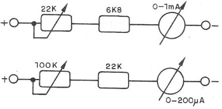
To make trimpot adjustment is simple. Also, connect the DC-volt meter to the maximum voltage.
Set the source to the maximum voltage and at the same time the trimpot so that the VU goes to the end of the scale.
See how much corresponds this indication in the own multimeter, noting the value in the VU.
Then it is only to divide in equal parts the scale, noting the corresponding values.
Assembly
The complete diagram of the source with touch control is shown in figure 3.
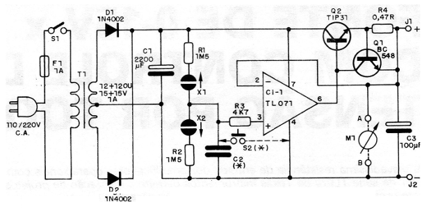
We can perform the basic part of the design on a printed circuit board, as shown in figure 4.
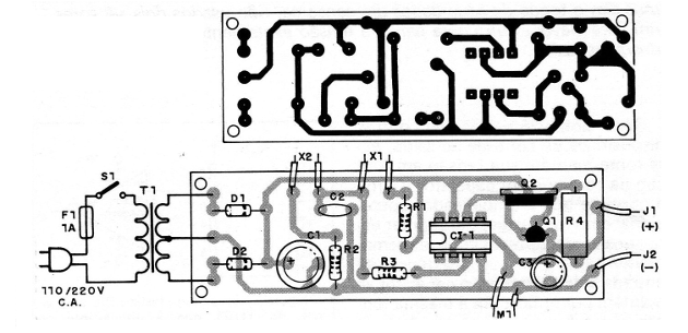
For the integrated circuit we can use a socket, and for Q2 a good heat radiator should be used.
C1 must have an operating voltage, at least 100% greater than the voltage of the transformer used.
We suggest 2 200 uF x 25 V for 12 V and 2 200 uF x 35 V transformers for a 15 V transformer.
The sensors can be fixed in the source panel itself, and there are several possibilities for this.
We suggest the configuration shown in figure 5, which consists of 4 brass screws, which provide good touch contact.
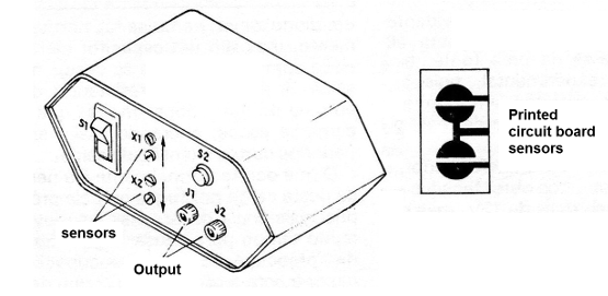
Another possibility is the use of a printed circuit board, according to the drawing.
We do not include it in the LED diagram for monitoring, but this can be done, remembering that it should be connected right after D1 in series with a 1k5 resistor.
The resistor R4 must be of wire with at least 1 watt of dissipation, and C3 can have a working voltage of 25 V.
The resistors are all 1/8 or ¼ W, except R4, as we explained earlier.
Test and Use
To prove the procedure is simple. Turn on the power by pressing S1.
Plug a multimeter or voltmeter into the outlet if you have not already incorporated it.
Tap sensor X1 first. The output voltage should rise slowly until it reaches the maximum. By touching X2 the voltage must drop. The rise or fall should stop the moment we stop touching the sensors.
If the voltage drops as soon as we stop touching the sensors, it is a sign that the capacitor C2 is leaking and must be replaced.
To use the source take into account the polarity of the output and especially the current limits. Do not connect a load that consumes more than expected.
When connecting electronic devices to the output, always proceed as follows: first adjust the voltage and then operate the powered device.
Cl-1- TL071, TL081 or CA3140 – FET Operational Amplifier (Texas or equivalent)
D1, D2 -1N4002, 1N4003 or1N4004 silicon diodes
Q1 - BC548 or equivalent - general purpose NPN transistor
Q2 - TIP31 or equivalent - NPN power transistor
T1 - 12 + 12 V or 15 + 15V x 1A transformer - primary according to local network
F1 -1A - fuse
S1 – On-Off switch
S2 – Push button
J1, J2 - red and black terminals (insulated)
M1 - see text (voltmeter)
C1 - 2 200 uF x 25 or 35 V - electrolytic capacitor
C2 - 2.2 to 5.6 uF - polyester capacitor (see text)
C3 - 100 uF x 25 V - electrolytic capacitor
X1, X2 - sensors (see text)
R1, R2 -1M5 x1 / 8W - resistor (brown, green, green)
R3 - 4k7 x 1/8 W - resistor (yellow, violet, red)
R4 - 0.47 ohm x1 W - wire resistor
Several: mounting box, power cable, printed circuit board, wires, fuse holder, heat sink for Q2, solder, etc.


