
Note: This article was published in Saber Eletrônica Issue No. 195, 1989. - ART3813S ART5278
A digital capacitance meter is a very useful instrument both in the designer's laboratory and in the repair shop. In the first case, in certain projects we need to know the exact value of a capacitor, not just the value marked on its casing; in the case of the repair technician, the capacitance meter will serve to indicate whether or not a suspect capacitor should be replaced.
The digital capacitance meter presented in this article reads capacitances in the range of 100pF to 10,000 µF, presenting the result in four significant digits, that is, through four displays. Using two SE-MC1 counter modules, this circuit can be housed in the same cabinet as the previously published Digital Chronometer and Frequency Counter, simply by adding a multiple switch so that the same counter modules can be used for one instrument or the other.
To increase the accuracy of readings, our instrument has eight measurement scales: three in nanofarads (inF), three in microfarads (pF), and two in millifarads (mF). The capacitance meter also has an "overflow" indicator, that is, an LED that signals the improper use of the device's scales.
DIGITAL CAPACIMETRY FEATURES
- 9V power supply (source or battery).
- 250mA consumption.
- LED overflow indicator.
- Measurement time no longer than 10s.
- Uses CMOS integrated circuits.
- Adjustments via trimmers.
- Eight reading scales.
- Measures capacitors ranging from 100pF to 10,000 µF.
OPERATING PRINCIPLE
There are several methods for measuring capacitance. We can, for example, set up a triangular signal generator and then a differentiator with the capacitor as the element under test; the result will be a rectangular signal with an amplitude proportional to the capacitor's value. By applying this signal to a voltmeter, we can easily measure the component's capacitance.
Another widely used method is the so-called "capacitance-to-frequency converter," which consists simply of an astable multivibrator controlled by a monostable whose period is determined by the value of the capacitor under test. Typically, capacitance meters based on this principle are implemented with two 555 (or one 556) integrated circuits and are coupled to a digital frequency counter.
In our project, however, we do not use any of the aforementioned ideas. The capacitance meter presented in this article is based on the discharge times of the capacitor being measured. The equation that provides the instantaneous values of the voltage across the capacitor during its discharge is:
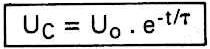
where:
Uc = instantaneous voltage across the capacitor, in volts
Uo = voltage at which the capacitor was charged, in volts
e = base of Neperian logarithms (e = 2.72)
π = time constant (π = R. C), in seconds
t = time - independent variable, in seconds
Now, if we allow the capacitor under test to discharge for only a time constant ('r = RC), we will have:
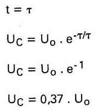
This means that after this interval, the voltage across the capacitor is equal to 37% of the initial charging voltage. Since we used a charging voltage of 9V, after 1π, we will have 3.33V across the capacitor.
So, what we do in our capacitance meter is allow the capacitor to be measured to discharge for only 1π, during which time the clock pulses generated by an oscillator reach the counter modules, which then record the capacitor's own value.
However, for this to happen, we need a control circuit that constantly "reads" the voltage across the discharging capacitor and compares it to the 3.33V reference. Nothing better for this function than using an operational amplifier as a voltage comparator. At the non-inverting input of the operational amplifier, we have the voltage across the capacitor, and at the inverting input, a voltage divider provides the 3.33V reference.
Thus, the comparator output remains at a high logic level as long as the capacitor voltage is greater than 3.33V (37% of 9V); on the other hand, it goes low when this voltage is equal to or less than the reference. For those who enjoy math, here is a literal demonstration that the number recorded by the counters (t) is actually proportional to the capacitor value (C), with the proportionality constant being equal to the discharge resistor value (R):
t = Discharge period = 1π = R . C
t = R . C
C = t/R
Which means that to know the value of a capacitor, all you need to know is its discharge time and the corresponding resistor. Since the resistor is known, as it is part of the circuit, all that remains is to measure the discharge time; and the counter modules perform this function.
The function of the adjustments made to the instrument, before final use, is to change the values of the resistor (R) and the number representing the discharge time (t) until the quotient tJR is numerically equal to the value of the capacitor, that is, its capacitance.
THE CIRCUIT
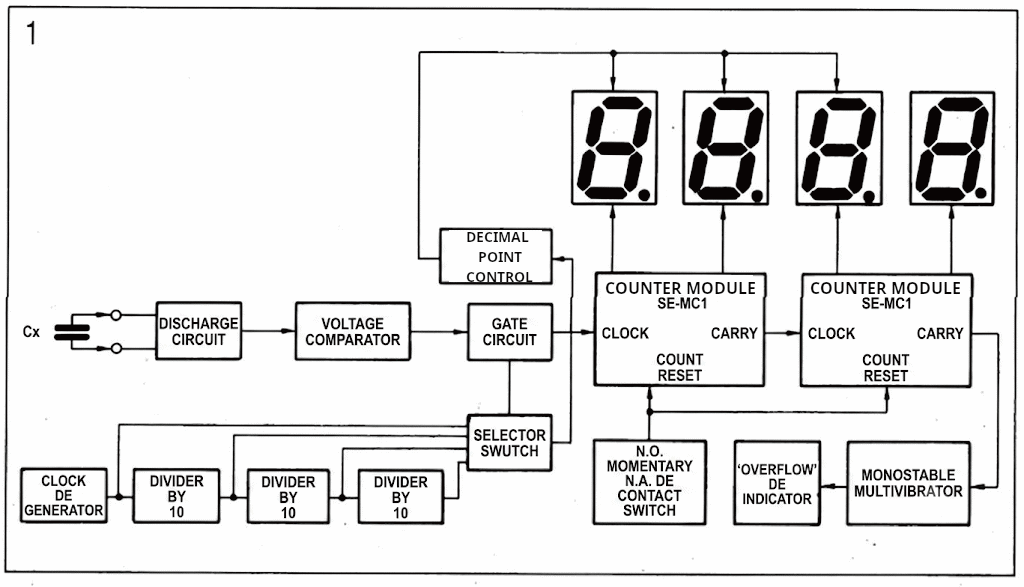
Figure 1 shows the block diagram of the digital capacitance meter, where we will begin describing how the circuit works. The first block is the discharge circuit, which consists of a transistor in common collector configuration. To its base, we connect a parallel RC circuit, where the capacitor in question is the component to be measured.
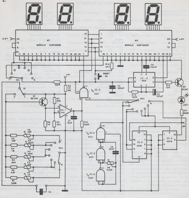
As can be seen from the schematic diagram in Figure 2, we have five different discharge networks selected by switch S2a. Each of these networks will be used for a specific range of capacitance values. Trimmers P1 to P5 adjust the correct impedance of each network for the respective capacitance range; these adjustments must be made with precision capacitors, as explained in the "Calibration and Use" section.
Switch S1, with 1 pole and 2 positions, is used to charge and discharge the capacitor under test. In the charge position, it connects the capacitor directly to resistor R9, causing it to charge with the source voltage (+9V); Note that this charge is practically instantaneous, since resistor R9 is only 1π, which gives us a very small time constant (π = R. C). After charging the capacitor, switch S1 is moved to the discharge position, connecting the element under test to the resistive networks selected by switch S2a. While the capacitor is discharging, transistor Q1 will conduct, and the voltage across its emitter resistor will be greater than zero.
Since the emitter voltage of this transistor is applied to the input of a voltage comparator, during the discharge period, and only while the voltage across the capacitor is greater than 3.33 V (37° of 9 V), we will have a positive voltage at the output of the operational circuit, which will enable the next block of the diagram: the "gate circuit." It should be noted that the 3.33 V reference is obtained through a resistive voltage divider designed as follows:
UREF = [ (R8 x Vcc) / (R7 + R8) ]
UREF = [ (3300 x 9 ) / (5600 + 3300) ]
UREF = 29700 / 8900
UREF = 3,33V
The block we call the "gate circuit" is nothing more than a CMOS NAND gate (produced through the 4011 integrated circuit). This gate's function is to allow clock pulses to pass to the counter modules only while the capacitor under test is discharging. Thus, the counters will record a number proportional to the capacitor's discharge time, that is, its capacitance. By adjusting the trimpots, we can easily make this proportional number coincide with the capacitor's own value, thus obtaining the reading directly from the displays.
The pulses applied to the input of the NAND gate, which will excite the counter modules, are generated by a CMOS oscillator formed by the three remaining gates of the 4011. This oscillator has its frequency calculated by the formula:
f = 1 / (1,4 x R x C)
Where R is in ohms, C is in farads, and f is in hertz. In our circuit, we calculated the components to obtain a frequency of 100 kHz, replacing the resistor with a trimmer, as this is the only way to adjust the oscillator precisely to the desired frequency.
After the clock generator, we have three dividers by 10, which are actually counters from 0 to 9. For this purpose, we use two CMOS 4518 integrated circuits, as each of them has two internal decade counters. This results in 10kHz, 1kHz, and 100kHz signals, which will be applied, along with the 100kHz signal, to the second pole of switch S2 (S2b). This switch will select which signal will be applied to the counters, according to the capacitance range.
The third pole of switch S2 (S2c) is used to control the display's decimal point illumination, depending on the instrument's scale. In Table 1, where we relate the switch positions to their respective capacitance value ranges, we can see how the decimal point illumination varies.
KEY POSITION= READING RANGE
1 = 00,01nF a 99,99nF
2 = 000,1nF 999,9nF
3 = 0001nF a 9999nF
4 = 00,01µF a 99,99µF
5 = 000,1µF a 999,9µF
6 = 0001µF a 9999µF
7 = 000,1mF a 999,9mF (*)
8 = 0001mF a 9999mF (**)
(*) theoretically, since we cannot build capacitors with such high values
(**) teoricamente, pois não podemos construir capacitores de valores tão elevados
TAB 1
Switch S3, a momentary contact switch, resets the counters; the reset must be activated by the capacitance meter user before taking the measurement. As for the overflow indicator, it consists simply of a monostable multivibrator triggered by the "go one" output of the last counter. The integrated circuit used for this function is the famous 555, whose trigger pin can be connected directly to the counter's "go one" output, as they are compatible.
This stage of the circuit works as follows: when the count on the last counter of the module changes from 9 to 0, the logic level of the "go one" output changes from 1 to 0. Because this pulse is being applied to the trigger input of the monostable, the output of this circuit immediately changes to logic 1, remaining there for the duration of the timing period. This period can be calculated by the formula T = 1.1. R13. C4, where R is in ohms, C is in farads, and T is in seconds. With the component values indicated in the diagram, this time is around 10 seconds, which we consider more than enough to alert the user that the reading should be taken on a larger scale.
To power the entire device, you can use either a 9V battery or the power supply shown in Figure 3.
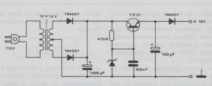
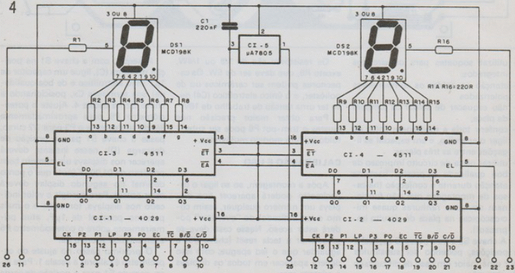
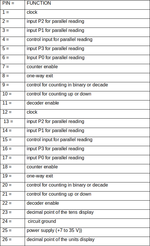
Figure 4 shows the schematic diagram of the SE-MC1 counter module, published in Issue N° 182 and Table 2 summarizes the functions performed by each pin of this module. This will facilitate the assembler's understanding of the circuit.
ASSEMBLY
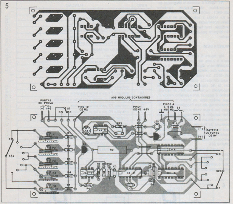
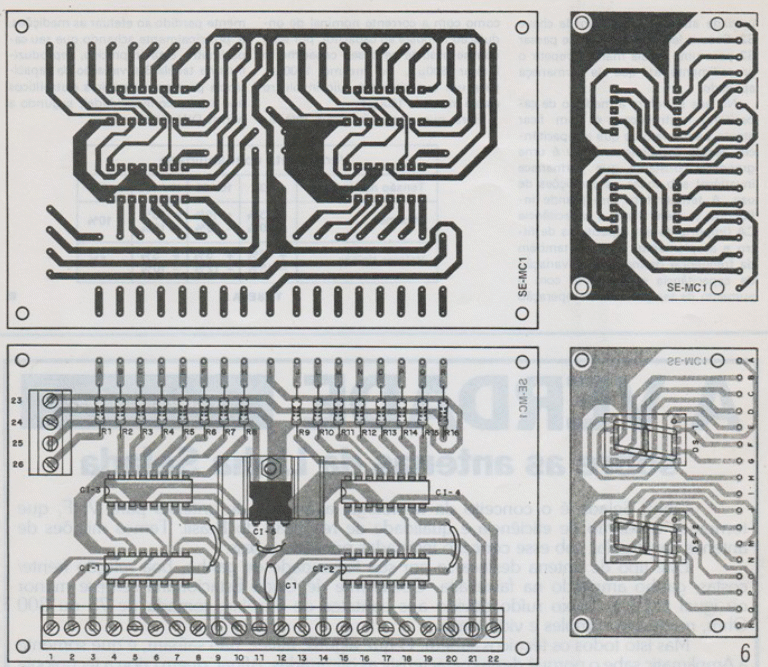
Figure 5 shows a suggested printed circuit board for the digital capacitance meter, and Figure 6 shows the layout of the SE-MC1 counter module's boards. If you want a more compact device, you can combine the three boards (the capacitance meter and the two modules) into a single board. However, if your goal is to have a modular device that can use the same counter modules as your Digital Frequency Meter (if you have assembled one!), the best solution is to assemble the boards independently and interconnected by common connection wires. Also, remember that the counter module boards can be purchased through Saber Postal Reimbursement (see advertisement on page 20).
tab2 SE-MC1 counter module pin out
As for the actual assembly, it does not present any major difficulties, and you should only remember the conventional precautions and recommendations, such as:
— Use sockets for integrated circuits;
— Be careful when soldering polarized components;
— Don't forget to solder the board's jumpers;
— Check the entire assembly before turning on the device, especially the connections between the three boards;
— Use a good-quality printed circuit board and pay close attention during assembly (there are cases of assemblies that don't work due to almost microscopic grooves in the printed circuit board!).
Switch S2 has 3 poles (3 sections) and 8 positions, and can be replaced with a larger one if you have difficulty obtaining one.
Resistors are 1/8 or 1/4W, except for R9, which should be 5W. Capacitors can be ceramic or polyester and the only electrolytic (C4) must have a working voltage of 16V. For greater precision in adjustments, trimpot P6 can be replaced with a multi-turn model.
CALIBRATION AND USE
After assembly, when the capacitance meter is turned on, any number may appear on the displays, and the "overflow" indicator LED may be on. In this case, press the reset key (switch S3) and wait for the LED to turn off; all displays should show zero.
Next, with switch S1 in the charge (C) position, connect a 1µF capacitor (non-electrolytic and of good quality) to terminals Cx, positioning switch S2 on scale 4. Adjust potentiometer P6 to approximately 3/4 of its travel and P3 to 1/2 of its travel; move switch S1 to the discharge (D) position; at this point, a number very close to 0.100µF should appear on the displays (note that the decimal point in the second display should be lit). To correct the value indicated on the displays, making it as close as possible to 1µF, first act on potentiometer P6 and then on P3.
The next step in adjusting the capacitance meter is to calibrate scale 1. To do this, switch S1 to the charge position and connect a 10nF capacitor (1% tolerance) to the Cx terminals. After pressing the "reset" key, move S1 to the discharge position, observing whether the number indicated on the displays is close to 10.00nF; if not, adjust potentiometer P5 and, as a last resort, slightly adjust P6.
The same 10nF capacitor ± 1% tolerance can be used to adjust scales 2 and 3, for which the procedure is the same, and the adjustment potentiometer (P4) is unique for these two scales. As with the other scales, if necessary, the P6 adjustment can be slightly adjusted.
To calibrate scales 5, 6, 7, and 8, proceed in the same manner, using 10µF capacitors for scales 5 and 6 and 2200µF for the remaining two. Note that on scale 7, the 2200µF capacitor will appear on the displays as 002.2mF, just as on scale 8 it will appear as 0002mF, since the reading is in millifarads (10-3F). The calibration potentiometers, in these cases, are P3, P2, and P1, respectively.
It is important to remember that the accuracy of the capacitance meter will depend solely on the adjustments made; therefore, we recommend that they be adjusted repeatedly until a satisfactory result is obtained. Likewise, the calibration capacitors should have a very low tolerance, as the accuracy of the device depends on them.
Once the adjustments are complete, wax should be applied to all potentiometers to prevent the settings from being altered simply by transporting the instrument. To check the overflow indicator's operation, simply connect a capacitor larger than the full scale of the S2 position you are using to the instrument terminals. For example, if you want to measure a 22011F capacitor on scale 4, the overflow LED should light up.
Your instrument is now ready to use. If you want to test the value of any capacitor, simply connect it to the instrument terminals with S1 in the charge position, press the reset key (switch S3), and then move S1 to the discharge position. If the overflow LED does not light up, simply read the reading directly on the displays, checking the unit using the position of switch S2. If the LED lights up, move S2 to a higher scale and repeat the procedure until it remains off.
When measuring electrolytic capacitors, it is important to be aware that the capacitance of these components is not a constant quantity that remains unchanged under all operating conditions. Temperature has a great influence, and AC capacitance (important in filter and coupling capacitors) also depends on the measurement frequency. Capacitance variation increases both with increasing operating temperature and with the nominal ripple current applied to the capacitor; therefore, don't be alarmed if your capacitance meter indicates 800µF, or even 1100µF, for a capacitor whose case is marked 1000µF.
So that you don't get completely lost when taking measurements, and especially thinking that your capacitance meter is inaccurate, we reproduce in table 3 the variation in capacitance for type I electrolytic capacitors (high reliability), according to the DlN 41420 standard.
LIST OF MATERIAL
DIGITAL CAPACIMETRY BASE PLATE
CI-1 - µA741 – operational amplifier
CI-2 – CD4011 – CMOS integrated circuit
CI-3, CI-4 – CD4518 - CMOS integrated circuit
CI-5 - µA555 – timer integrated circuit
Q1, Q2 – BC547 – general-purpose NPN transistors
Led1 – common red LED
S1 – 1-pole x 2 position switch
S2 – 3-pole x 8 position rotary switch
S3 – momentary contactor switch
C1 – 10nF – ceramic or polyester capacitor
C2 – 22nF – ceramic or polyester capacitor
C3 – 220nF - ceramic or polyester capacitor
C4 - 100µF – 16V electrolytic capacitor
C5 – 100nF – ceramic or polyester capacitor
R1 – 100 ohms – resistor (brown, black, brown)
R2, R14 – resistors (yellow, violet, red)
R3 – 56k – resistor (green, blue, orange)
R4, R6 – 1M – resistors (brown, black, green)
R5 – 12M – resistor (brown, red, blue)
R7 – 5k6 – resistor (green, blue, red)
R8 – 3k3 – resistor (orange, orange, red)
R9 – 1 ohm x 5W – wire resistor
R10, R15 - 330 ohms – resistors (orange, orange, brown)
R11 – 220 ohms – resistor (red, red, brown)
R12 – 10k - resistor (brown, black, orange)
R13 – 100k – resistor (brown, black, yellow)
P1 – 1k- trim-pot
P2 – 10k – trim-pot
P3, P4 – 100k – trim-pot
P5 – 4M7 – trim-pot
P6 – 470 ohms – trim-pot
COUNTER MODULE
(must be assembled two)
CI-1, CI-2 – CD4029 – CMOS integrated circuits
CI-3, CI-4 – CD4511 – CMOS integrated circuits
CI-5 - µA7805 – voltage regulator
Ds.1,Ds.2 – MCD 198 K – common cathode displays
CI – 220nF – ceramic or polyester capacitor
R1 to R16 – 220 ohms - resistors (red, red, brown)
Miscellaneous: printed circuit boards, sockets for integrated circuits, heat sink for the voltage regulator, screw-on printed circuit connectors, 18-way parallel flexible cable, wires, solder, power supply or 9V battery, etc.


