
Note: Article published in Eletrônica Total magazine, issue 146, 2010. ART3921S ART5493
There are two operating possibilities for the magic pendulum we propose in this article. In the first, you swing the pendulum, and with a simple gesture, it stops its movement, as if by magic. In this case, the action of a sensor that can "see" its movement, performed in a special way, comes into play. In the second, you swing the pendulum, and with a beam of light from a battery-powered flashlight, or simply by lighting a match or lighter, the pendulum's movement is stopped.
Of course, there is an "electronic trick" to achieve this, but with a well-disguised setup, the magician will certainly fool many, demonstrating his powers of stopping movement from a distance.
The device we describe operates on electromagnetic and photoelectric principles and is powered by common batteries.
How It Works
When strong electric current flows through a coil made of many turns of thin enameled wire, a strong magnetic field is created that attracts metal objects. If a ferrous metal object with a core, such as a nail or screw, is placed inside this coil, it becomes a powerful magnet.
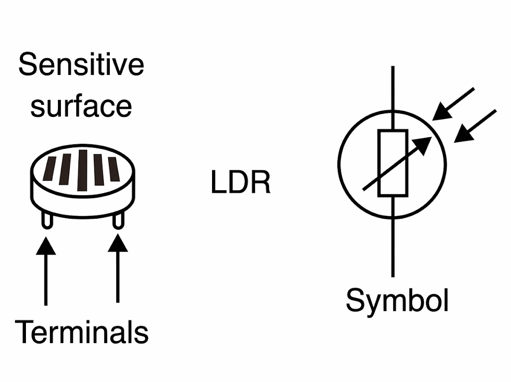
On the other hand, to control the current based on light, we use an SCR (silicon-controlled diode) and an LDR (photo resistor). The LDR is a device that, when exposed to light, decreases its resistance. This component, shown in Figure 1, has a sensitive cadmium sulfide surface with electrical properties.
The LDR is connected to the SCR, acting as a "switch" that can turn on when the LDR's resistance decreases or when it increases, depending on how it is connected to the circuit. In our case, we used the version in which the SCR turns on when the resistance increases, so that the pendulum can be triggered or stopped by the shadow of our hand passing in front of the LDR. In the version in which it turns on when the resistance decreases, the SCR is triggered by the flashlight's beam.
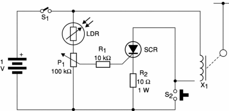
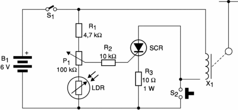
A P1 potentiometer in both versions adjusts the system's sensitivity, ensuring the SCR only triggers at the desired level of light or shadow. With proper adjustment, even without ambient light, we can trigger from several meters away with a standard flashlight, or even the shadow of our hand.
The magnetic system consists of an electromagnet wound around 200 to 500 turns of fine enameled wire on a nail or screw.
This nail or screw must be hidden so that bystanders will not suspect its action. The pendulum, to be attracted by the coil's magnetic field, has a nut or other ferrous object at its tip.
In the shadow-triggered system, the circuit's operation can be summarized as follows: once potentiometer P1 is adjusted, the SCR is at the trigger threshold, that is, with a gate voltage slightly below the one it needs to turn on.
When the light falling on the LDR (ambient light) is interrupted by the shadow of the magician's hand, the SCR's gate voltage rises for a moment, enough to trigger it. This causes a strong current to flow through the electromagnet. This current is limited by resistors R3 and R2 (in the other version) to prevent the batteries from draining too quickly and the electromagnet from overheating.
The current through the electromagnet creates a strong magnetic field that acts on the pendulum, attracting the nut at its tip, causing its swinging motion (impressed by the magician before the operation) to stop instantly.
Assembly
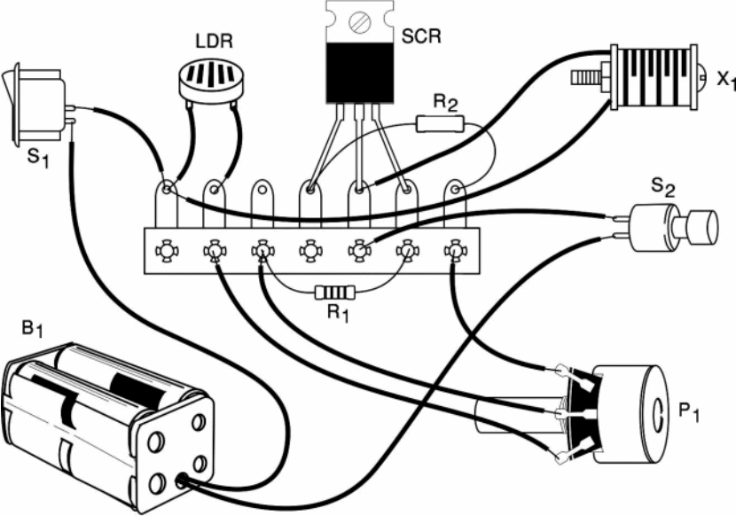
We begin by presenting the two electronic circuits. The one in Figure 2 is for the version that triggers with light. This assembly can be made using a terminal bridge, as shown in Figure 3. The version that operates by shadows has its circuit shown in Figure 4 and uses virtually the same components, except for the 4.7kohms resistor.
We can also assemble it using a small terminal bridge. See Figure 5. The SCR is a TIC106 for any voltage, and a heat sink is not necessary. The LDR can be a large type (FR-27 from Tecnowatt or equivalent). Smaller LDRs are equally sensitive and can be found in old televisions with automatic brightness controls. With luck, you can get this component free.
The resistors are 1/8 W or larger, except for R2 in the first version and R3 in the second, which should be 1W, as they tend to heat up. Potentiometer P1 can be set to any value between 100 kΩ and 470 kΩ. Trimmers of the same value can even be used for greater savings.
For batteries, we use appropriate holders, and S1 is a simple switch that can even be eliminated if the reader is careful to remove the batteries when not in use.
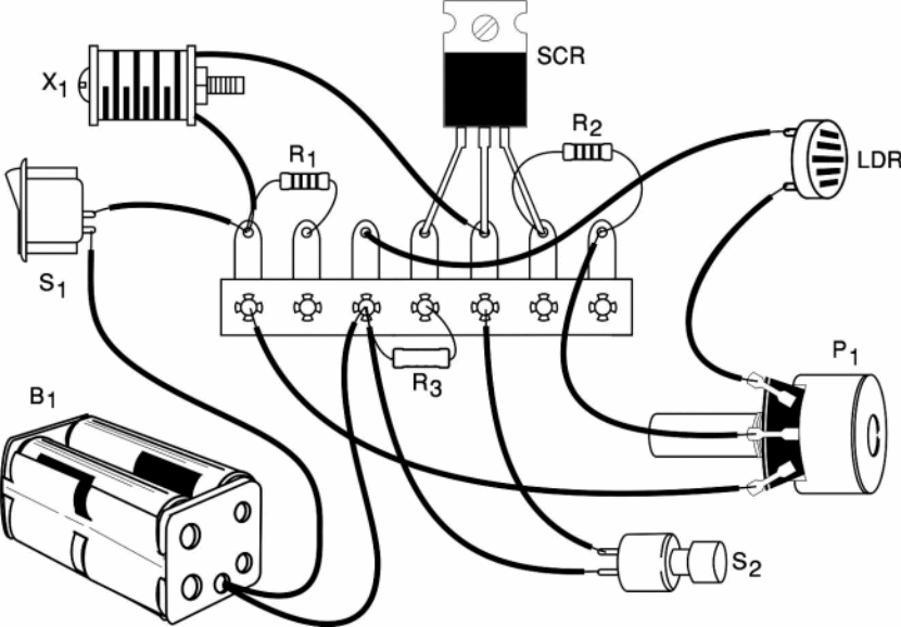
S2 is an NA pressure switch, a "doorbell button" type, but if this is not available, two short, stripped wires (which will be placed next to each other to reset the device) can be used.
The final appearance is crucial in assembly, as is the electromagnet X1, which is wound around a screw approximately 2 cm long and 0.5 cm in diameter. 200 to 500 turns of fine enameled wire should be wound (the more turns, the stronger the magnetic field).
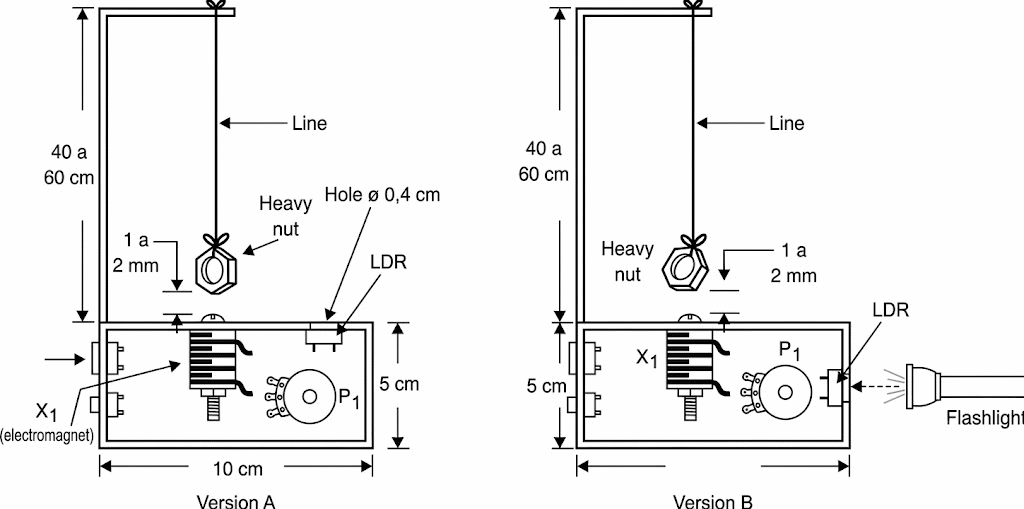
Figure 6 shows the mechanical part of the assembly and the placement of the components in a box. Note that the position of the LDR depends on the desired actuation type. A bent wire serves to support the pendulum, which is tied with a piece of thin string. The washer should pass no more than 2 mm from the screw so that the attraction as it passes is sufficient to stop its movement.
The box can be made of wood or even cardboard, and the hole for the passage of light that should fall on the LDR should be 0.5 to 1 cm in diameter. Note the controls on the back of the box: on/off, sensitivity, and reset.
Operation
Adjusting the two versions involves different procedures:
Light-triggered version
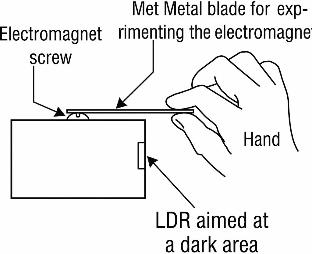
Position the LDR so that it does not receive direct light from intense sources such as a ceiling lamp, a window, or even the sun, as shown in Figure 7.
Turn on S1 and, using a small piece of metal placed near the electromagnet, turn potentiometer P until the trigger occurs. The small piece of metal should be strongly attracted to the magnet. Adjust the setting slightly and press S2 briefly to reset the system.
Now, push the pendulum so that it swings freely. Point a flashlight at the LDR and produce a flash, or light a lighter nearby, also producing a flash. The circuit should trigger, stopping the pendulum's movement.
Shadow-Triggered Version
To adjust this version, let ambient light shine on the LDR, for example, from the ceiling, a window, or another source. Turn on S1 and, using a blade or metal object near the electromagnet, adjust P1 until the circuit is at the triggering threshold, as in the previous version.
Back off the P1 setting slightly when the triggering occurs and press S2 briefly to reset it. The circuit should trigger, stopping the pendulum's movement.
To perform the magic in front of an audience
Invite your friends to the demonstration, taking care to position and test the device on a table beforehand. Explain that, with a gesture of your own, or with a lighter, you can stop the pendulum from moving, and that this is due to your "magical powers" or even the power of thought. Turn on the unit without your friends noticing and set the pendulum in motion (while doing this, take the opportunity to turn on the circuit).
Then, simply make a shadow gesture over the LDR, or light the flashlight or lighter, and the pendulum will stop. To repeat the demonstration, briefly press S2. Do this when you put the pendulum back in motion. As soon as the movement stops, reset the circuit, even if the pendulum is not set in motion again, to avoid draining the batteries too quickly.
Materials list
a) Version 1 – light activation
SCR – TIC106 or MCR106 – silicon diode
Resistors: (1/8 W, 5%)
LDR – common LDR – photo resistor
R1 – 10 kΩ (brown, black, orange)
R2 – 10 Ω x 1 W (brown, brown, black)
P1 - 100 kΩ – potentiometer
Miscellaneous
X1 - Electromagnet – see text
S1 – Single switch
S2 – Pressure switch
B1 – 6V – 4 small or medium batteries
Mounting box, battery holder, terminal bridge, thick wire, nut, screw, thin enameled wire, etc.
b) Version 2 – shadow actuation
Semiconductors:
SCR – TIC106 or MCR106 - silicon controlled diode
Resistors: (1,8 W, 5%)
LDR – Common LDR – photo resistor
R1 – 4,7 kΩ (yellow, violet, red)
R2 – 10 kΩ (brown, black, orange)
R3 – 10 Ω x 1 W (brown, black, black)
P1 – 100 kΩ – potentiometer
Miscellaneous:
X1 - Electromagnet – see text
S1 – Single switch
S2 – Pressure switch
B1 – 6V – 4 small or medium batteries
Terminal bridge, mounting box, battery holder, enameled wires, nuts, screws, thick wire, solder, etc.


