
Note: Article published in the magazine Mecatrônica Jovem (Brazil) – Jogos em 2023 - ART3340S ART5294
Over the years, we published two versions of the game center in the magazine Saber Eletrônica. One of them became a kit. The operating principle of both is the same, with the only difference being the way the random pulses are generated. Both are available on our website at the end of the article.
In the first version, we used a unijunction oscillator that can also be simulated with two bipolar transistors. In the second version, we use a 555 integrated circuit, which is more common today than the single-junction one and even allows for a more compact assembly.
Before analyzing the basic version's operating principle, let us explain the purpose of our game. Nothing prevents you from analyzing the circuit and making any desired changes, of course, remembering to modify the printed circuit board if necessary.
An Interesting Game Center
There are many types of electronic games: some are adaptations of traditional games like dice, roulette, and coin toss, which can be made much more interesting with the help of random devices that simulate the results they produce.
There are intelligence games in which the circuits are programmed to perform certain moves according to pre-established rules, aiming to beat the human opponent, as in the case of electronic chess, and finally, skill games in which the electronic circuit simply acts as a "proctor," signaling when the player commits a foul, as in the case of "nervo-teste" (figure 1).
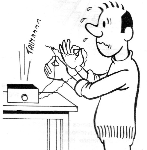
Our game center falls into the first group, that is, the category that simulates games of chance, in which a position, number, or indication is drawn completely outside the player's influence. (See the article "How to Generate Random Numbers" in this magazine)
It is, therefore, an "electronic lottery machine" that is resistant to fraud and player influence and can be used in a variety of interesting games.
The reader should note that traditional games based exclusively on luck are myths, avoiding any player influence at all costs. We cite as an example one of the most traditional games: dice, where the established rules vary greatly depending on the game played.
Our game is not limited to a single application like dice, “rapa-tudo”, is adapted so that it can be used in any of the mentioned modalities. In short, what we have is a drawing device, as we said, that can be used in different game modes, always acting efficiently, without letting the player influence the result.
It can even be used in paranormal experiments using Zener cards. See the article (in portuguese – use the translator) at:
https://www.newtoncbraga.com.br/index.php/blog/1113-telepatia-e-telecinesia-pn006.html
The modalities mentioned in this article are just some of the possible ones, since the reader with imagination can create their own games or applications and with them have fun or do serious research work with the generation of random numbers.
However, the modalities suggested in this article, being the most traditional and most interesting, will undoubtedly give the reader plenty of reasons to create their own.
The suggested games are as follows:
a) sports lottery
b) electronic dice
c) poker
d) scramble
e) pinball
f) casino
Figure 2 shows how a single device can be used in different modes.
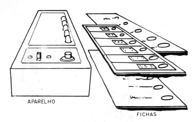
The drawing circuit remains, but the cards on its panel that establish the rules, values, and how to play each game are no longer used. At the end of the article, the reader will find instructions for playing each game with this device.
Version 1 – With a unijunction, transistor and a 6-value card (commercial kit sold at the time)
Figure 3 shows a block diagram that allows us to understand the operating principle of this mini-game center.
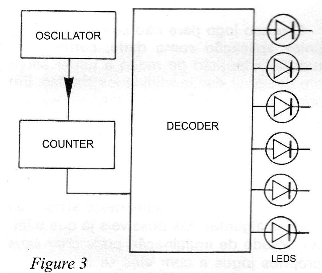
It is a random-switch circuit in which an oscillator produces an indeterminate number of pulses that cause a counter to illuminate a certain number of LEDs in sequence, leaving only one illuminated at the end.
The oscillator that produces the pulses is based on a unijunction transistor that oscillates, controlled by the charge of a capacitor. When this capacitor slowly discharges after the game starts, the successive flashing of the LEDs gradually decreases, thus providing a vital sense of suspense. (Figure 4)
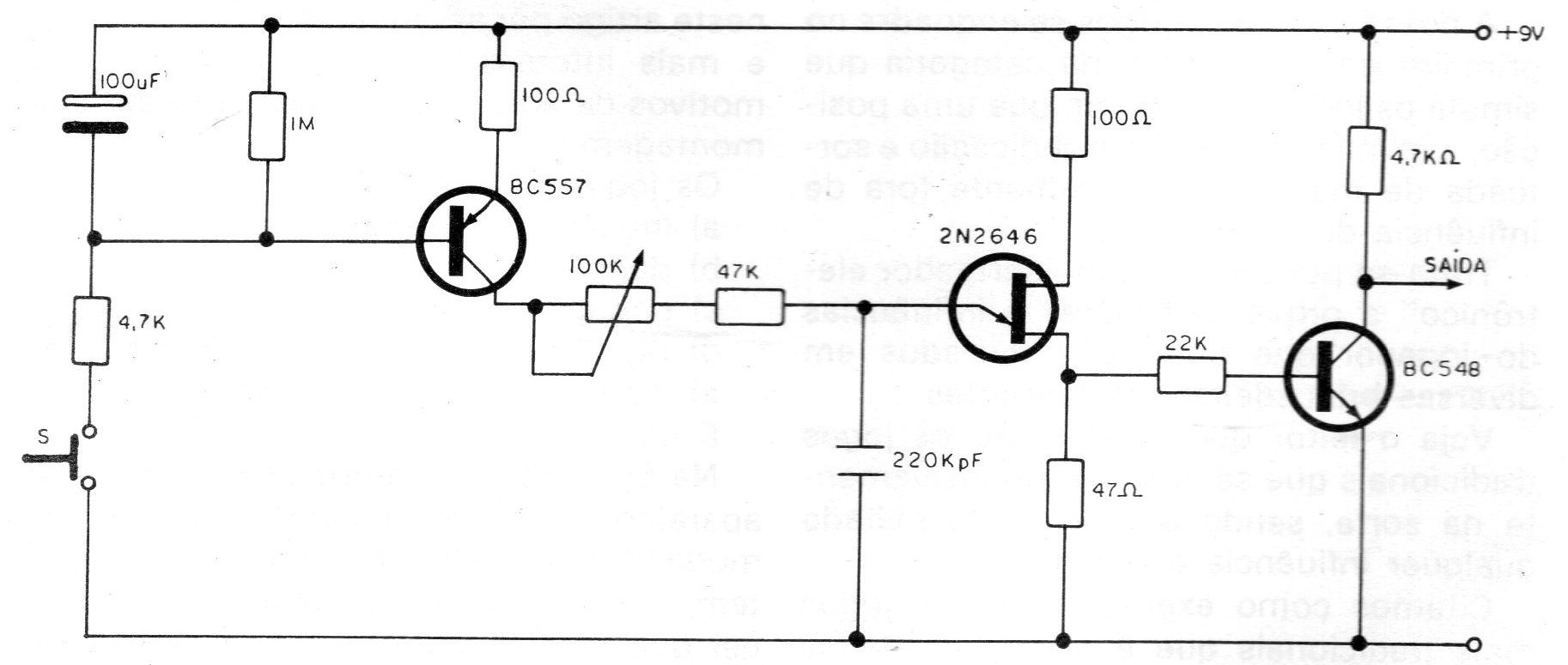
Thus, in the oscillator circuit, we have two important components whose values can be changed if the reader wishes to modify its operating characteristics: C1, which determines the time the LEDs blink before turning on their stop, and C2, which determines the blinking speed, that is, the time each LED remains lit. By increasing the values of these components, we also increase the cycle time they control.
The signal from this oscillator is sent to a CMOS 4017 digital integrated circuit, a 5-step Johnson counter, which in this case is wired to count up to 6. Thus, with each oscillator command pulse, it distributes the signal among 6 outputs successively, thus turning on the LEDs in succession at the same pulse speed (Figure 5).
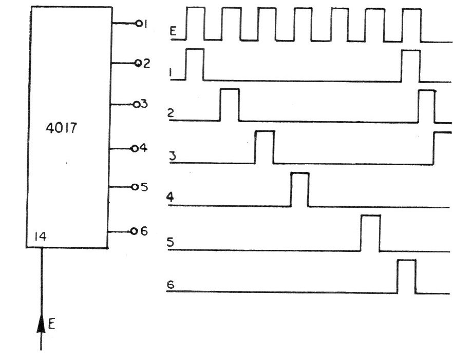
Since the power of the pulses obtained from the six outputs of the integrated circuit is insufficient to drive the LEDs with sufficient power, six "driver" transistors are added to the circuit, to which the LEDs are connected.
Note: At the time, this circuit was developed, the LEDs required more current. The drive stage can be achieved by directly connecting the LEDs to the 4017 output, modifying the board according to the diagram in the second version, if desired.
The circuit is powered by a 9-volt battery, and the unit's power consumption is proportional to the time it remains on and the desired light intensity for the LEDs. In this setup, the resistor values connected to the LEDs were sized to combine a good lighting effect with good battery life.
Assembly – Version 1
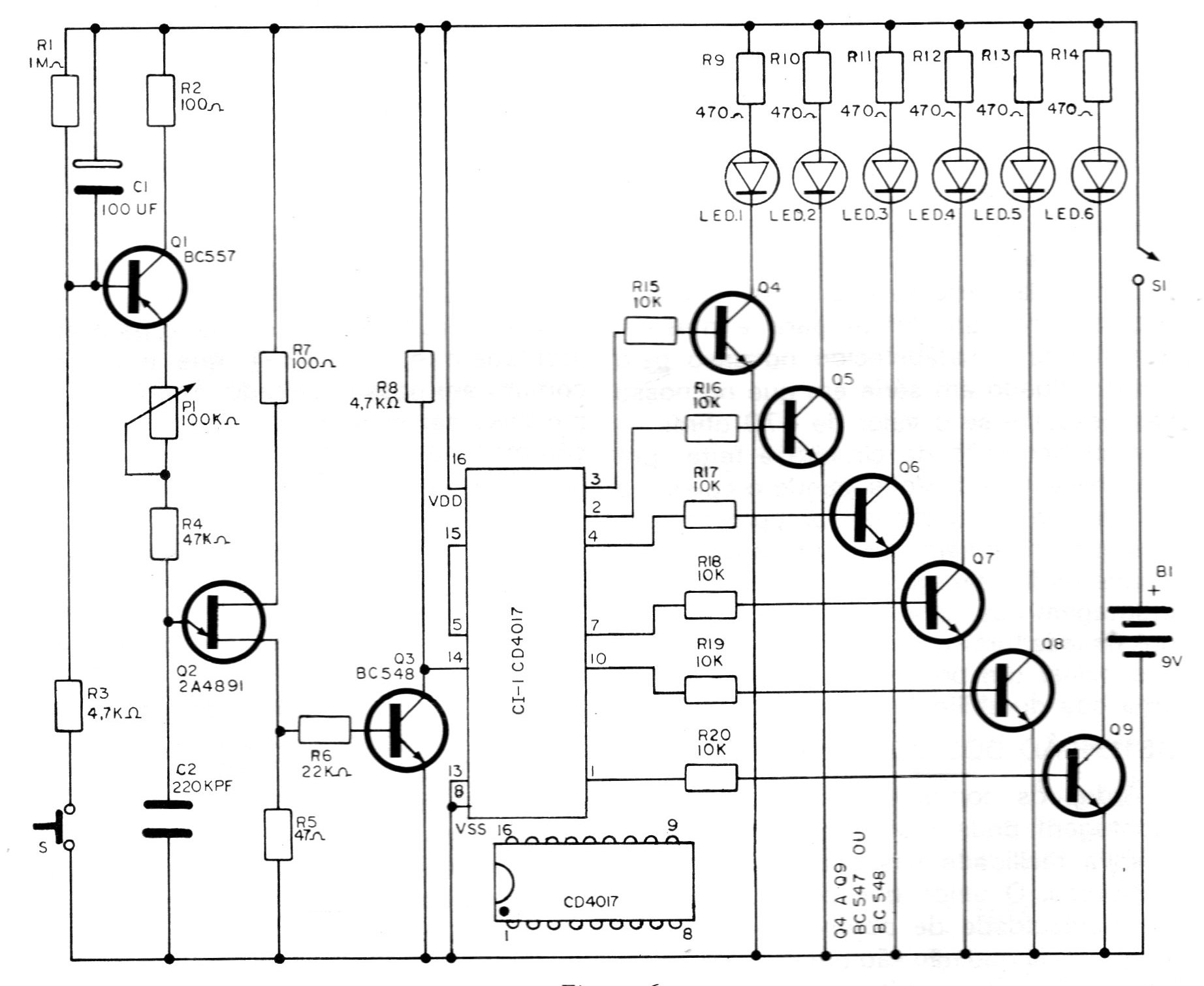
Figure 6 shows the complete diagram of the gaming center, and Figure 7 shows the printed circuit board used.
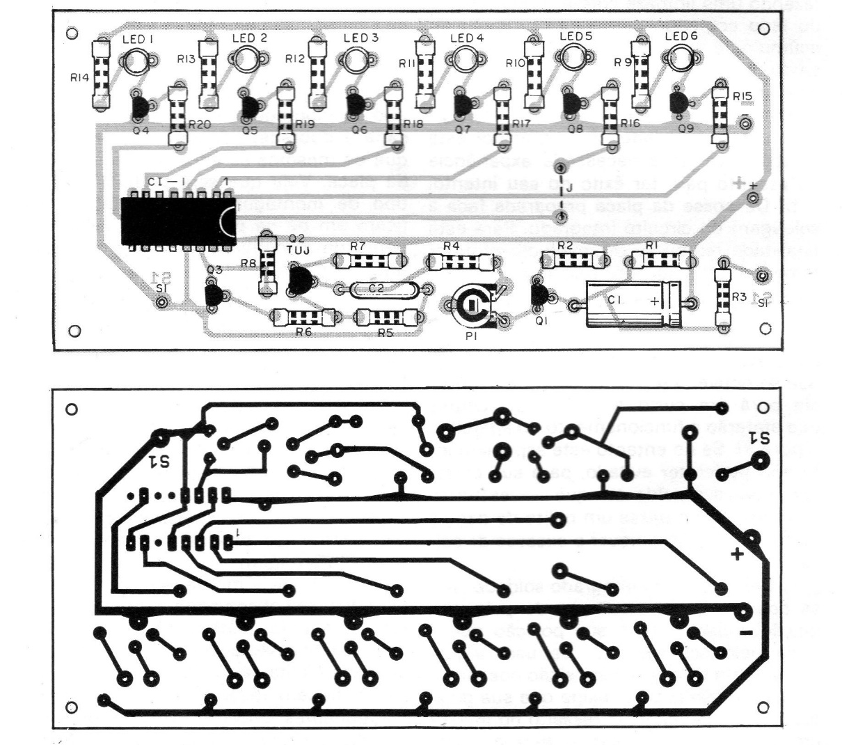
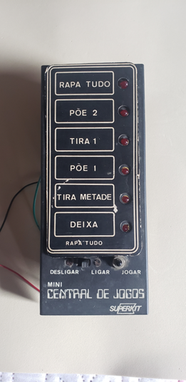
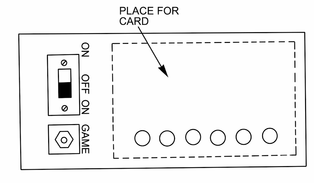
Note the position of the integrated circuit, transistors, and LEDs on the board, which have a location for their flat side (cathode). Figure 8 shows the box on its front with the controls and LEDs.
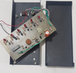
The photo shows the assembly of the original kit we have in our collection. It is the original assembly of the prototype that was later manufactured and sold by Superkit.
Version 2 – Using the 555 IC
In this version, we have two possibilities. Use a 10-position card with changes to the box and the cards themselves, or use the random generator as indicated and the counter circuit from the previous version with minor changes to the board.
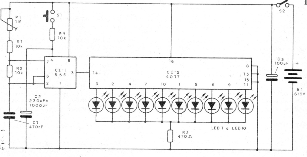
In it we have an oscillator with a 555 integrated circuit that generates random pulses at a frequency adjusted by trimmer P1. The pulses are applied to a 4017 decade counter, which drives one of 10 LEDs. (See our article on random pulse generation.)
When we press S1, the counter is activated and the LEDs run rapidly until S1 is released. Since the pulses are random, we cannot know how many have been counted, nor can we know which LED will stop counting. Therefore, the selected LED is random.
Figure 10 shows the complete diagram of the device.
The device assembly based on a printed circuit board is shown in Figure 11.
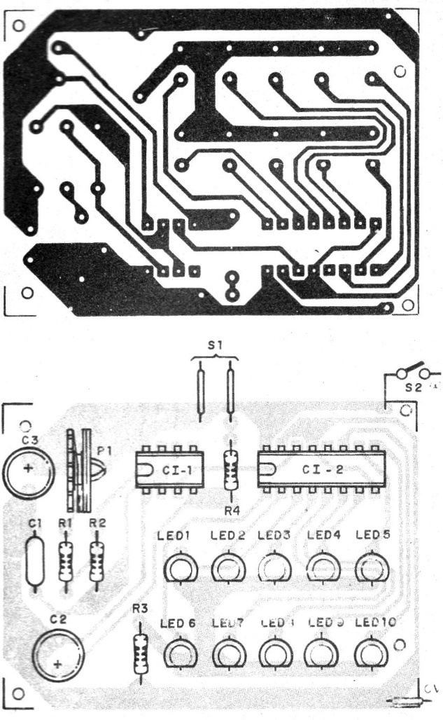
Note the correct position of the integrated circuits. Power can be supplied with 4 batteries or a 9 V battery. The device can be mounted in a plastic or metal box where the game plugs fit.
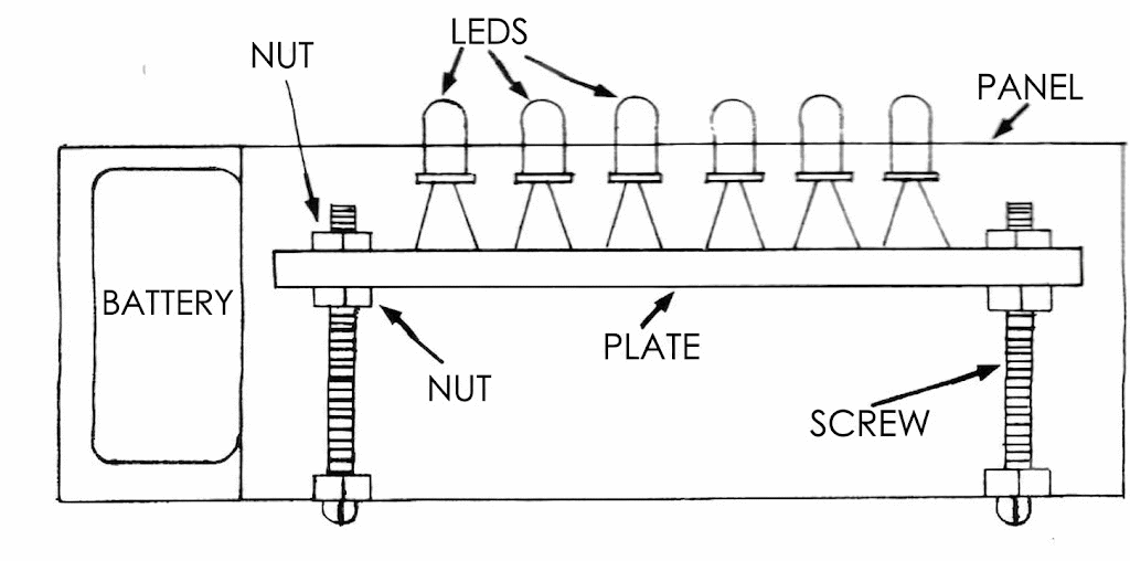
Figure 12 shows that the LEDs should be left with the longer terminals so that they stick out through the holes in the box, an important assembly detail.
The cards
We have several possibilities for both the 6-position version, the original kit, and the 10-position version. Of course, the assembler can create their own sets.
6-position version:
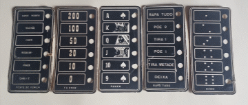
THE GAMES
With the device assembled, you must prepare the cards that will be placed on the game center panel, as appropriate. These cards can be drawn on cardboard or copied directly from the template we provide. The game rules are given below; these are just a few suggestions for contests you can hold with your electronic game center.
Electronic Sports Lottery
A sports lottery or betting prediction game for individual or group play. In this application of your game center, you will place a card with 6 possible predictions for sports lottery games. Figure 13 shows the card to be used in this version.
To play in a group, each player simply places a bet and lets the device choose the winner. Each player makes their bet by marking it on a chalkboard or using chips, and then the "banker" draws the winner. The winner takes all, and if there is no winner, the "banker" takes all.
POKER
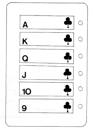
Figure 14 shows the appearance of the card that should be used for this game.
To play "electronic poker," the procedure is as follows:
The player will need a sheet of paper to write down their combinations:
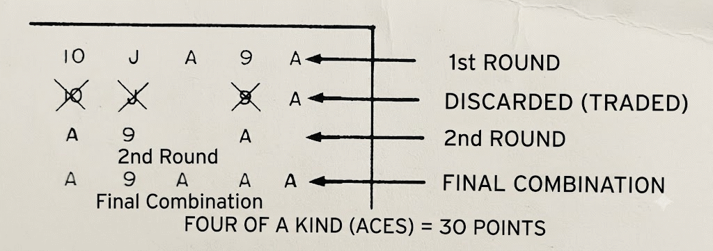
a) First, play 5 times, writing down the results you get, as shown in Figure 15.
b) Examine your combination. If you didn't get a maximum straight, that is, the numbers in progression 9, 10, J, O, and K or 10, J, O, K, and A, you can try again, canceling one, two, or three of the cards you got and making a new bid.
c) Write down the results of the new bid.
d) With the results obtained in the first series minus the canceled ones and plus those obtained in the second attempt, you will have 5 cards written down.
Depending on the type of combination obtained, you will have a certain number of points, as suggested below:
- Maximum straight, that is, consecutive cards (all 5) - 50 points.
- Flush - 5 of the same cards - 40 points.
- Four of a kind - 4 of the same cards (regardless of which one is left) - 30 points
- Full hand - 3 of the same cards plus a pair = 20 points
- Three of kind - 3 of the same cards - 10 points. - Pair - 2 identical cards - 5 points for each pair
If there is a tie, the tiebreaker will be based on the value of the cards. For example, four of a kind of 10 beats four of a kind of 9. To play, the player can proceed as in real poker, placing bets in the first round and then in the second.
ELECTRONIC DICE
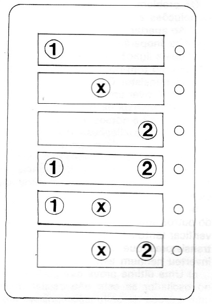
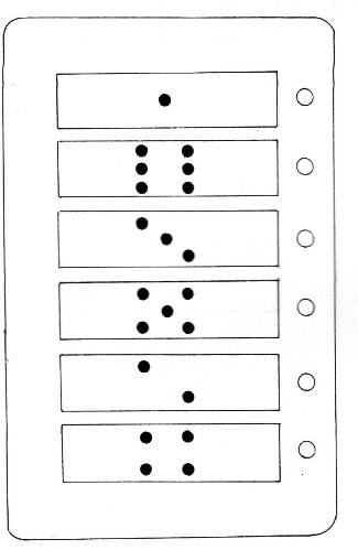
Figure 16 shows the appearance of the card that can be used in this application of your mini-game center. The dice can be used in various types of games or decisions.
To make the game interesting, use betting chips.
Take it All
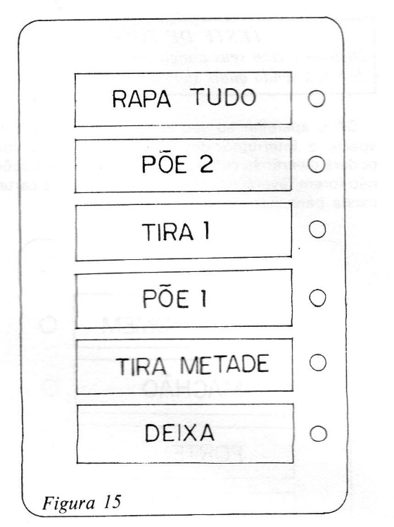
Figure 17 shows the card that should be used for this game.
The rules are simple:
Each player starts with a set number of chips and, in turn, activates the device's switch, doing what the LED that remains lit tells them to do. For example, if the LED lands on POE 1, the player must place a chip on the table. If it lands on RAPA TUDO, the player must remove all the chips accumulated in the previous moves.
MINI FLIPPER
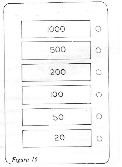
See how many points you can score in 10 rounds. The card for this game is shown in Figure 18.
The rules are simple: with each turn, you must record the number of points you earn. Agree on a number of rounds with your friends and see who can get the most points.
TEST OF STRENGTH
Have fun with your friends with this strength simulator, seeing who is weak and who is strong. Give the device to your friend and have them press the pressure switch. At a party, you can have fun at the expense of those whose scores are not favorable. Figure 17 shows the card used for this version of the game.
CASINO
Place bets on this mini-roulette wheel and be the big winner. Figure 20 shows the card for this game. Each player must bet on the number they think will come up, and the banker presses the switch. If there is a winner, they take all. If not, the banker keeps the chips.
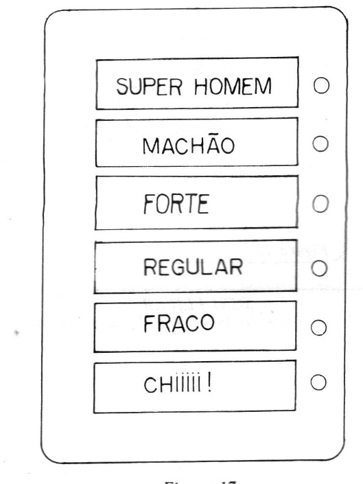
Figure 21 shows some suggested cards that can be adapted for the 10-LED version.
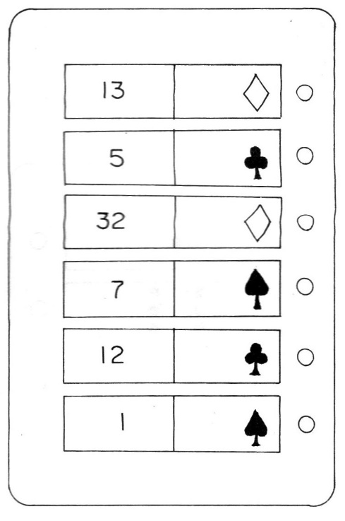
For the 7-position card version, we have
Testing and use is simple. Turn on the power and press S1. When you release S1, only one LED should remain lit after it stops running.
Material List - Version 1
CI -1 - CD4017 or equivalent
Q1 - BC 557 or equivalent - PNP transistor
Q2 – 2N2645 or equivalent - unijunction transistor
Q3. Q4. Q5. Q6. Q7, Q8, Q9 - BC548 or equivalent (NPN transistor)
LED1 to LED6 - red light-emitting diodes
P1 - 100k trimpot
C1 - 100 uF x 16 V electrolytic capacitor
C2 - 220 nF (polyester)
R1 - 1M ohm x 1/8 W resistor (brown, black, green)
R2 - 100ohm x 1/8 W resistor (brown, black, brown)
R3 - 4.7 k ohm x 1/8 W resistor (yellow, violet, red)
R4 - 47 k ohms x 1/8 W resistor (yellow, violet, orange)
R5 - 47 ohms x 1/8 W resistor (yellow, violet, black)
R6 - 22 k ohms x 1/8 W resistor (red, red, orange)
R7 - 100 ohms x 1/8 W resistor (brown, black, brown)
R8 - 4.7 k ohms x 1/8 W resistor (yellow, violet, red)
R9, R10, R11, R12, R13, R14 - 470 ohms resistors (yellow, violet, brown)
R15, R16, R17, R18, R19, R20 - 10 k ohms x 1/8 W resistors (brown, black, orange)
S - pressure switch
S1 - single-ended switch
Miscellaneous: 9 V battery connector, 9 V battery, printed circuit board, mounting box, cards, wires, solder, screws, nuts, etc.
Material List - Version 2
CI-1 – 555 – integrated circuit
CI-2 – 4017 – integrated circuit
LED1 to LED10 – common LEDs – see text
S1 – Pushbutton switch
S2 – Simple switch
P1 – 1M – potentiometer or trimpot
C1 – 470 nF – ceramic or polyester capacitor
C2 – 220 nF to 1 uF – capacitor
C3 – 100 uF – electrolytic capacitor – 12 V or higher
R1, R2, and R3 – 10 k ohms x 1/8 W – resistors – brown, black, orange
R4 – 470 ohms x 1/8 W – resistor – yellow, violet, brown
Miscellaneous:
Mounting box, printed circuit board, battery holder or 9 V connector, wires, game cards, solder, etc.


