The TLE 4921-3U differential Hall sensor can be used in applications such as speed detection of rotating magnetic parts, speed detection and encoder position; and further serves to generate trigger signals.
It operates in differential mode with the combination of two hall cells and a differential amplifier, which makes it possible to work with field differences rather than absolute intensities.
This configuration also compensates for the external effects of temperature, component tolerances and influence of external magnetic fields.
For these reasons, this sensor is especially suitable for operation under aggressive conditions. A small permanent magnet is required to polarize the systems that will generate the pulses, such as gears of various shapes.
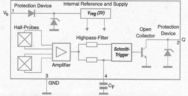
Thus, appropriate switching even for the smallest field differences between the tooth and the void is guaranteed. The minimum guaranteed switching frequency is 10 Hz with the use of a 470 nF filter capacitor. In figure 1 we have the block diagram of this sensor integrated circuit.

When the Hall sensor is exposed to a constant magnetic field of any polarity, the two elements generate the same output signals. The difference is zero, regardless of the intensity of these fields. However, if there is a field gradient from one sensor to another, then a signal difference is generated, for example, if a sensor is focused on one tooth of one gear and another on the space between them.
This signal is amplified on the chip. If there is a slight difference, due to sharpening problems it can be canceled by control mechanisms. The dynamic differential response of the device gives it great sensitivity even though there is a relatively large gap between the gear and the sensor surface.
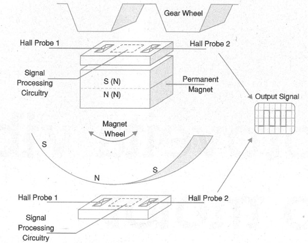
A Schmitt trigger can be used to scan the conditioned signal and the output is made by an open collector transistor, which has a good current drain capability, thus providing the external signal. The chip is equipped with overvoltage and reverse polarity protection as well as EMI, which allows its application in hostile environments. In figure 2 we have a typical application of this component.

In this figure we have the typical use of the sensor in detecting the passage of the teeth of a gear. Note the presence of the bias magnet in the case of a gear made of nonmagnetized material. In addition, we have the use of the sensor in the case in which the movement must be detected in a magnetized piece.
The orientation of the magnetic field of this part is important so that the sensor can generate the external control signal.
The two Hall sensors of the integrated circuit are mounted with a 2.5 mm separation. See that the cog of the gear acts as a field concentrator. It increases the magnetic flux density in the sensor and thereby a differential signal is produced. With the movement of the gear, the differential signal changes polarity at the same rate at which it moves.
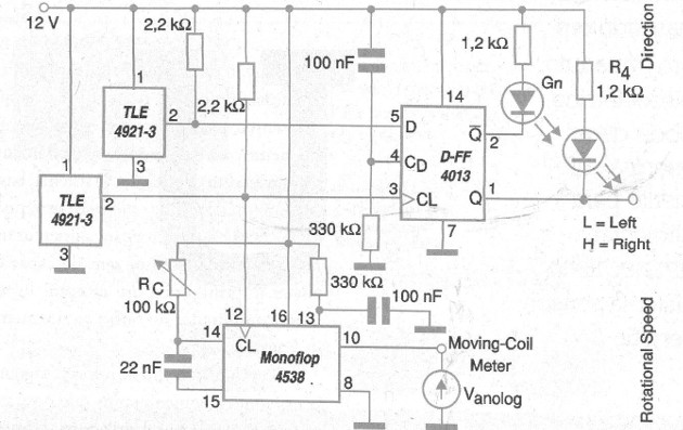
The integrated high-pass filter regulates the signal through the time constant that can be adjusted by an external capacitor. Note the waveform of the signal obtained at the output. In figure 3 we have a circuit for rotational measurement.

In this application we see the 2.2 k resistors used as pull-up in the open collector outputs of the TLE 4921-5U transistors. Also note the presence of LEDs indicating the direction of rotation of the gear.
The moving coil indicator (analog) is set in the monoflop to indicate the corresponding rotational speed of the gear. Of course, changes can be made to this circuit, such as the use of a digital display.


