This project has been included in one of my books on electronic espionage. The book had the original edition in the 80's, thus, an old tape recorder is indicated, but modern digital equivalents can be used.
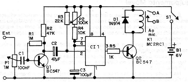
In figure 1 we have an example of a timed Vox circuit.

When a signal arrives via the microphone cable, it is sufficient to trigger the 555 monostable for a time interval which depends on the setting of P1. This setting is such that the recorder does not stop between short intervals between the words or phrases of the speakers.
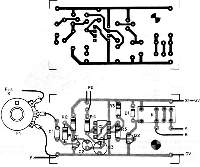
In figure 2 we have a printed circuit board suggestion for this project.

P2 adjusts the sensitivity depending on the minimum sound level required for the activation of the device.
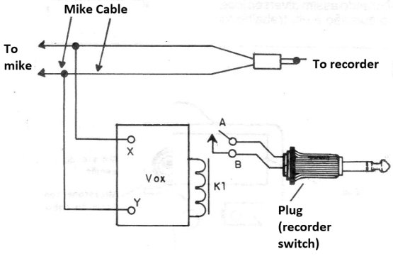
The relay contacts act on the microphone switch of the recorder, usually on the small cassette recorders or digital used in this type of work.
Figure 3 shows how to use the appliance.

SEMICONDUCTORS
Cl-1 - 555 - integrated circuit
Q1 and Q2 - BC547 or equivalent - general purpose NPN transistors
D1 - 1N914 - general purpose diode
RESISTORS
P1 - 1 M - potentiometer
P2 - 100 k - potentiometer
R1 - 1M - resistor (brown, black, green)
R2 - 47 k - resistor (yellow, violet, orange)
R3 - 22k - resistor (red, red, orange)
R4 - 10 k - resistor (brown, black, orange)
R5 - 1 k - resistor (brown, black, red)
CAPACITORS
C1 - 100 nF - ceramic or polyester capacitor
C2 - 47 uF x 12V - electrolytic capacitor
C3 - 100 uF x 12V - electrolytic capacitor
SEVERAL
K1 - Relay 6V x 100mA
B1 - 4 medium or large batteries
Printed circuit board, battery holder, wires, solder, mounting box, etc.


