This article is part of a spy book that we published in the 1980s and was updated in 2015.
The principle of operation is based on a LDR photocell (photo-resistor) that must be permanently illuminated by a small lamp. When the light beam incident on this cell is interrupted, circuit tripping occurs.
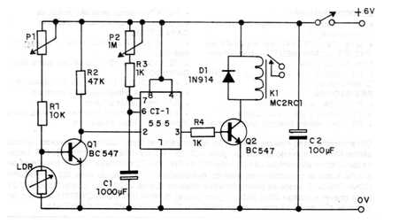
In figure 1 we have the complete circuit of this interesting automatism that also functions as an alarm.

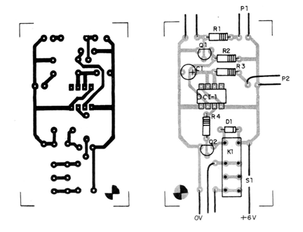
The printed circuit board is shown in figure 2.

P1 adjusts the sensitivity as a function of ambient light, while P2 adjusts the timing from a few seconds to about 1 hour, depending on the value of the electrolytic capacitor connected to pins 6 and 7 of the integrated circuit.
The maximum recommended value of this capacitor is 2 200 uF since larger values can destabilize the circuit due to leakage. The relay terminals are connected to the microphone key of a recorder or to a transmitter for clandestine listening, and at the same time to a remote alert system to know what is happening.
To use the device is simple:
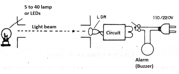
Position the LDR so that it receives light from the small lamp hidden in the passage (2 a15watts); The LDR and lamp can be fitted with tubes with lens to direct the light.
Set P2 to the shortest timing position and then open P1 until the relay trips. Come back a little and wait. If the relay does not open, turn it back a little until the trigger threshold is reached. Try moving your hand in front of the LDR to interrupt the light beam.
Checking the operation is just to do the installation. In figure 3 we have the way to do this installation, activating a recorder and at the same time m remote warning.

SEMICONDUCTORS
CI-1 - 555 - integrated circuit
Q1 and Q2 - BC547 or equivalent - general purpose NPN transistors
D1 - 1N914 - silicon diode
RESISTORS
P1 - 100 k - potentiometer
P2 - 1M or 2.2M - potentiometer
R1 -10 k - resistor (brown, black, orange)
R2 - 47 k - resistor (yellow, violet, orange)
R3 and R4 - 1 k - resistor (brown, black, red)
CAPACITORS
C1 - 1000 uF at 2 200 x 12V pF - electrolytic capacitor
C2 - 100 uF x 12V - electrolytic capacitor
SEVERAL
K1 - 6 V x 100 mA Relay
B1 - 6 V - 4 medium batteries (alkaline)
S1 - single switch
Printed circuit board, mounting box, wires, solder, etc.


