Sound comes out with good volume on a speaker, but nothing prevents a higher-power external amplifier from being used.
Two complementary transistors are used and the power can be made either with 3 V voltage or 6 V, which corresponds to two or four common small batteries. The assembly is very simple, being able to be done in bridge of terminals or printed circuit board.
OPERATION
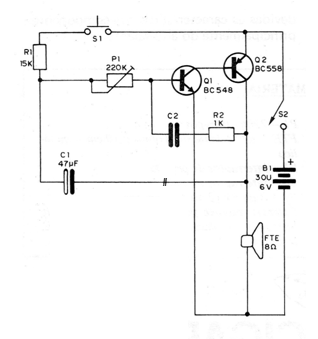
What we have is a simple oscillator that uses two complementary transistors, that is, one NPN and another PNP, that form an amplifying stage.
The feedback signal taken from the speaker is brought back to the input of the circuit by R2 and C2 which determine the pitch of the sound obtained and its frequency. For the bass sound of an ox moan we use a capacitor of 1, uF, but close values, such as 470 nF or 560 nF, can be used with changes in the P1 setting.
This P1 trimpot just controls the operating point of the oscillator.
The lowing effect is obtained by an additional resistor and capacitor, which are R1 and C1. When the switch is pressed, C1 is charged via R1, then the oscillator frequency rise occurs which then decreases when S1 is released. The value of C1 then determines the duration of the moo, and can be changed at will by the experimenter.
A critical point of this circuit is the loudspeaker, which must be 8 ohm x 10 cm, metallic or heavy. The mechanical structure of this speaker determines the timbre of the oscillations so that they imitate the mooing.
With other types of speakers, experiments show that the sound obtained does not match the desired sound.
ASSEMBLY
In figure 1 we have the complete circuit of the ox.

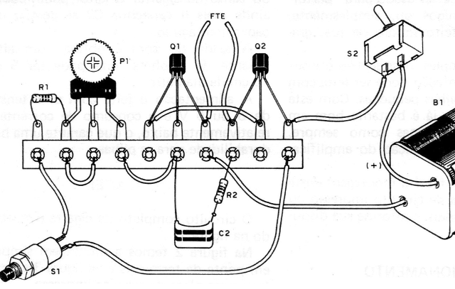
In figure 2 we have the simplest version that is in bridge of terminals.

Figure 3 shows the printed circuit board version.

The following care must be taken during assembly for perfect operation:
a) Be careful not to change the transistors Q1 and Q2. They are of different types and their position is given by the flat side of their casing. Solder them quickly so that the heat does not damage them.
b) When soldering C1, observe its polarity which is marked on the enclosure itself. Be careful not to invert it.
c) In the welding of C2 be quick so that the heat does not damage it.
d) The resistors have their values ??given by the colored bands. See the material list if you have questions.
e) When soldering the trimpot, slightly open its terminals, if its assembly is bridged, to fit the point of connection. In the plate version you need to widen the holes so that the terminals fit.
f) Complete the assembly with the S1 connection, the speaker and the battery holder. For the latter it will be necessary to observe its polarity.
Once the assembly is complete, run the test.
PROOF AND USE
Insert the batteries in the holder and, if all is in order, activate S2 (this switch is optional, since in the S1 position the power consumption is minimal and when not in use the batteries can be removed from the holder).
The speaker should be on a table with its mouth down so that there is resistance to cone movement, which will help to get the proper resonance for the desired sound. Pressing S1 and releasing it, set P1 to obtain the beeping of the ox.
If there is a tendency for different oscillations, try to change the position of the speaker initially. If the sound has a different tone than expected, the player can compensate for this by changing the value of C1 and C2.
The small differences that occur are due to the characteristics and tolerances of the components, especially the loudspeaker.
Q1 - BC548 or equivalent - NPN transistor
Q2 - BC558 or equivalent - PNP transistor
C1 - 4.7 uF x 6 V - electrolytic capacitor
C2 - 1 uF or 470 nF - polyester or ceramic capacitor
R1 ~ 15k x 1/8 W - resistor (brown, green, orange)
R2 - 1k x 1/8 W - resistor (brown, black, red)
P1 - 220 k - trimpot
FTE - speaker 8 ohm x 10 cm ~ metallic
S1 – push button
S2 - single switch
B1 - 3 or 6 V (2 or 4 small batteries)
Several. support for 2 or 4 batteries, terminal strip or printed circuit board, wires, solder, etc.


