If you need an output stage for a receiver or tuner, an output stage for headphones, an amplifier for an intercom, a battery mini-amplifier for a siren or other sound effect, this is recommended.
Using complementary output transistors, this circuit has excellent sensitivity and sound quality. As a test amplifier for your bench, this project will be of all-purpose utility.
HOW IT WORKS
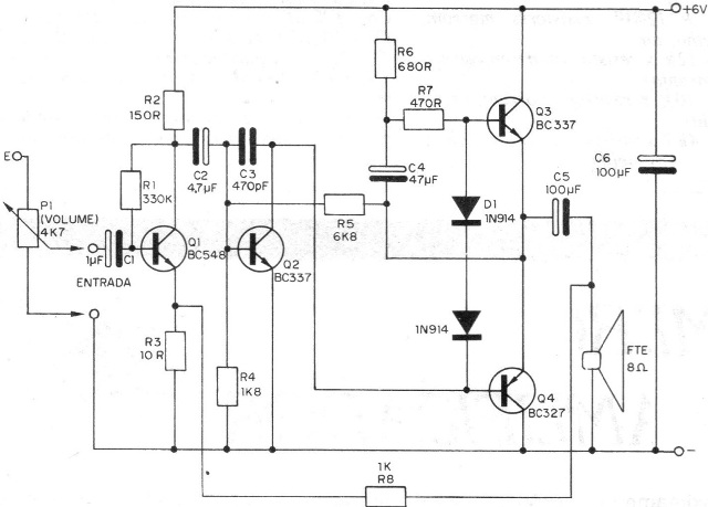
Four transistors are used in three stages of amplification, as suggested in figure 1.

The first step takes only one transistor and is a preamplifier in order to pick up small audio voltages from microphones, pickups, and other signal sources, amplifying them a first time to pass them to the next step.
The next step is the driver or driver that amplifies the audio signal a little more to the point where it can be used in the excitation of the next stage. A single low power transistor is used in this stage.
We finally have the output stage in complementary symmetry in which two transistors, one PNP and one NPN, are used.
While one amplifies half the half-cycles of the audio signal, the other amplifies the other half.
Due to its characteristics, this step provides an output with minimal distortion in the sound, and still with low impedance, which means that we can directly connect the 8 ohm speaker without the need for an output transformer.
ASSEMBLY
In figure 2 we have the complete circuit of the microamplifier with the values ??of all the components used.

The printed circuit board assembly can be done by following figure 3.

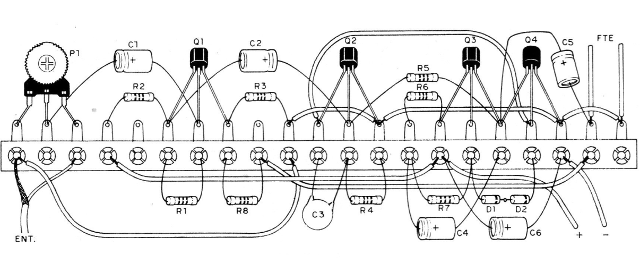
For the terminal strip version of terminals, less compact, follow figure 4.

The care that must be taken with the assembly is as follows:
a) Welding the transistors observe both their position that is given by the flat side of their enclosure as well as the types, since both NPN and PNP transistors are used.
b) When soldering the diodes D1 and D2 observe well its position that is given as a function of the rings. Be quick in welding these components.
c) Electrolytic capacitors are also polarized components and their position must be observed. See also their values.
d) The capacitor C3 which is ceramic does not have the right polarity for bonding, but is sensitive to heat. Be quick in your welding.
e) The resistors have their values given by the colored rings. Follow the list of material in your placement.
f) The input cable, where a volume control connection can be made, must be shielded with the mesh connected to the negative pole of the power supply so that there is no buzzing.
g) Observe the polarity of the power cord.
h) When using the loudspeaker, use flexible plastic wire not too long.
At the end of the assembly, check all the connections and, if everything is in order, make a functional test.
TEST AND USE
Turn on the power supply, observing its polarity. If a source is used, take care that it has good filtering, otherwise a nasty buzzing sound will appear on the speaker.
Touching the input terminal of the amplifier (Q1 base) with a finger should hear loud snorting on the speaker, indicating proper operation of the amplifier.
When using it, observe the sensitivity limitations by not applying too strong signals at the input that may be responsible for distortions.
Q1 - BC548 - Silicon NPN Transistor
Q2, Q3 - BC337 - silicon NPN transistor
Q4 - BC327 - silicon PNP transistor
D1; D2 - 1N914 - silicon diodes
C1 - 1 uF x 6 V - electrolytic capacitor
C2 - 4.7 uF x 6 V - electrolytic capacitor
C3 - 470 pF - ceramic capacitor
C4 - 47 uF x 6 V - electrolytic capacitor
C5, C6 - 100 uF x 12 V - electrolytic capacitors
P1 - 4k7 - trimpot
R1 - 330 k x 1/8 W - resistor (orange, orange, yellow)
R2 - 150 R x 1/8 W - resistor (brown, green, brown)
R3 - 10 R x 1/8 W - resistor (brown, black, black)
R4 - 1k8 x 1/8 W - resistor (brown, gray, red)
R5 - 6k8 x 1/8 W - resistor (blue, gray, red)
R6 - 680 R x 1/8 W - resistor (blue, gray, brown)
R7 - 470 R x 1/8 W - resistor (yellow, violet, brown)
R8 - 1k x 1/8 W - resistor (brown, black, red)
FTE - 8-ohm speaker (any size)
Miscellaneous: printed circuit board, 6 V supply (batteries or network), mounting box, wire, shielded wire, etc.


