We can transmit sound telegraphs imperceptibly using ultrasound, as we described in Professor Ventura's story available on the website in the corresponding section. With it, students send the answers of a test through ultrasound, being the signals received by a special receiver.
Well, we describe in this article the assembly of both the transmitter and the receiver, hoping that readers will use the system for didactic purposes or in trade shows, not in the original application of the story ...
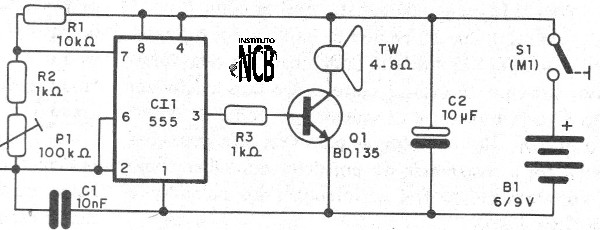
The transmitter consists of an oscillator with 555 that is set to operate at a frequency between 18,000 and 22,000 Hz, which can be reproduced in good yield by a small piezoelectric tweeter. A power transistor feeds the tweeter, making it possible to emit a few tens of meters.
This transmitter is powered by 4 common batteries and has its circuit shown in figure 1.

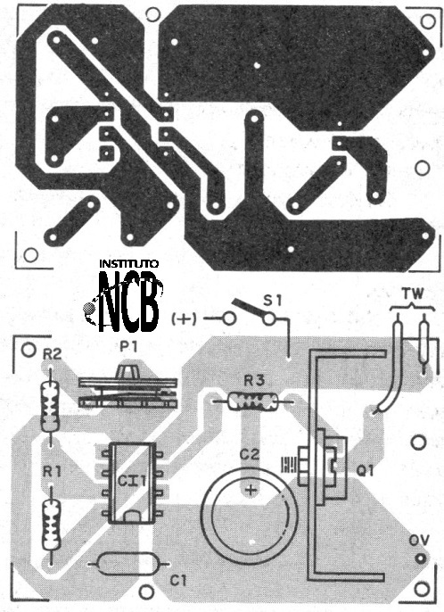
The assembly may be made on a printed circuit board as shown in Figure 2.

When mounting the transmitter, note the position of the integrated circuit and transistor, which should have a small heat sink. The manipulator can be improvised with metal plaques or a pressure switch can be used.
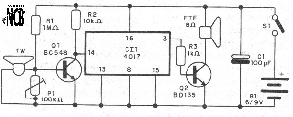
The resistors are 1/8 W with any tolerance and the electrolytic has a working voltage of 6 V or more. The receiver uses a small piezoelectric tweeter as a microphone (sensor) applying its signal to an amplifier transistor that excites a frequency divider with the 4017.
Dividing the frequency of the captured ultrasound it converts to sound and with that, when applied to a transistor, it can be heard on a small speaker or headset. In figure 3 we have the complete diagram of the receiver.

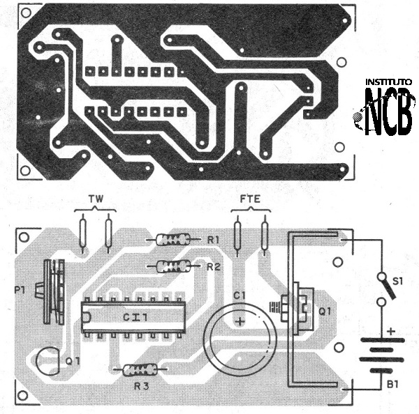
The assembly can be done on a small printed circuit board as shown in figure 4.

On assembly, note the position of the integrated circuit and transistors, as well as the polarity of the electrolytic capacitor. The resistors are 1/8W with any tolerance and the tweeter as a microphone must have the internal transformer removed so as to connect only the high impedance transducer to the circuit.
To test and use, turn on the transmitter, press the handler and adjust P1 so that the sound becomes very sharp and then disappears in the ultrasound range. Place the receiver in front of the transmitter and set P1.
The sound of the transmitter must be heard.
a) Transmitter
CI-1 - 555 - integrated circuit
Q1 - BD135 - medium power NPN transistor
S1 - Manipulator
B1 - 6 V - 4 small battery
TW- piezoelectric tweeter
P1 - 100 k ohm - trimpot
C1 - 10 nF - ceramic or polyester capacitor
C2 - 10 uF - electrolytic capacitor
R1 - 10 k ohm - resistor - brown, black, orange
R2, R3 - 1k ohm - resistors - brown, black, red
Several:
Printed circuit board, battery holder, mounting box, wires, solder, etc.
b) Receiver
CI-1 - 4017 - integrated circuit
Q1 - BC548 - NPN general purpose transistor
Q2 - BD135 - medium power NPN transistor
TW-piezoelectric tweeter - see text
S1 – On/Off switch
B1 - 6 V - 4 small batteries
P1 - 100 k ohm - trimpot
C1 - 100 uF - electrolytic capacitor
R1 - 1 M ohm - resistor - brown, black, green
R2 - 10 k ohm - resistor - brown, black, orange
R3 - 1k ohm - brown, black, red
Several:
Printed circuit board, battery holder, wires, solder, etc.


