Obs. This project after be published in a Brazilian Magazine was included in my book CMOS Projects and Experiments (Newnes 1999)
The frequency range can also be altered by changing the value of C2. The upper limit of the circuit is 1 MHz.
Biological experiments related to animal behavior and conditioning can be conducted using this oscillator. The power supply is formed by four AA cells or a 9 V battery.
The circuit drains only few milliamperes, extending the power supply life to several weeks.
R1 can be connected in series with a 47,000 ohm potentiometer to allow frequency adjustment in a wide range.
The schematic diagram or the Ultrasonic Generator is shown in fig 1.

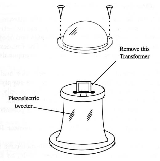
For the transducer, you can also use a piezoelectric tweeter. This component has a small output transformer inside, as shown in Fig 2. You have to disconnect the transformer to use the tweeter in this project.

Small piezoelectric transducers can also be used in this project.
IC 1, IC2 - 4093 CMOS integrated circuit
X1 - Piezoelectric Transducer or crystal earphone, Radio Shack 27 3-07 3 or equivalent
R1 - 27,000 ohm, 1/4 W, 5% - resistor
C1 - 100 µF, 12 WVDC - electrolytic capacitor
C2 - 0.001 µF ceramic or metal film - capacitor
S1 - SPST Toggle or momentary switch
B1 - 6 V (four AA cells) or 9 V (battery)


