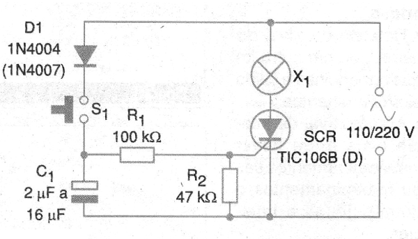
In figure 1 we have the complete circuit of the time light. The maximum interval is of the order of a few minutes and depends on C1.

Utilities:
• Lighting of hallway lights and elevator halls
• Timed activation of various loads such as fans and heating elements.
• Timing of industrial automations where high accuracy is not required.
Constructive Details:
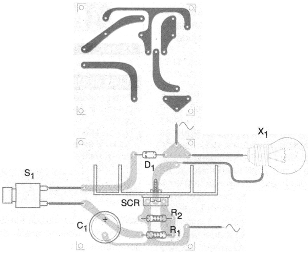
The printed circuit board for mounting the time light is shown in figure 2.

The capacitor C1 is a high voltage electrolytic, for 200 V if the grid is 110 V and 400 V if the grid is 220 V. The SCR must be mounted on a heat radiator. The values in parentheses are for the 220 V network.
The load must be resistive and the control is half wave.
Semiconductors:
SCR - TIC106B or D - SCR for 110 V or 220 V according to the local network
D1 - 1N4004 (110 V) or 1N4007 (220 V) - silicon diode
Resistors: (1/8 W, 5%)
R1 - 100k ohm
R2 - 47 k ohm
Capacitor:
C1 - 2 uF at 16 uF x 200 or 400 V - high voltage electrolytic - see text
Several:
X1 - incandescent lamp up to 100 W
Printed circuit board, heat radiator for SCR, wires, solder, etc.


