We have already pointed out in our articles that a microcontroller does not do everything by itself and that it needs peripheral or interface circuits to complete its function. It is the Shields that control motors, power loads, sensors and much more.
Thus, conventional electronics is absolutely necessary for any design which works with microcontrollers and for it there are many old integrated circuits that perfectly adapt to them. In this article, we will deal with some of these indispensable integrations in the designer workbench with Arduino and other microcontrollers.
Of course, there is the option of using modern equivalent circuits with LVC logic (3V Low Voltage Logic) and others which best fit the 3V power supply of the circuits, but in their absence one can work with old circuits and same 5V logic.
Common Circuits
In fact, all 5V CMOS (Complementary Metal-Oxide Semiconductor) and TTL (Transistor-Transistor Logic) circuits and 3V families can be used with microcontrollers. Most, however, are of the conventional type from a time when maximum operating speeds were slower and there were no certain decoupling features which are needed today. Thus, we can use our designs with Arduino, PIC (Peripheral Interface Controller) and other microcontrollers, CMOS integrated circuits like 4093, 4017, 4001, 4011, etc., without problems if application is not very critical or subject to noise problems. In fact, what we see nowadays is that a good deal of microcontroller designs, especially those using Arduino, suffer from coupling, noise, and interference pickup problems.
A circuit with a sensor which has a connection cable to the Arduino can pick up noise that will be interpreted with varying logic levels leading to erroneous operation. A pulse counter of a sensor may total more than the pulses produced, due to the sum of the noise, or not yet register zero in the absence of pulses, as shown in Figure 1.
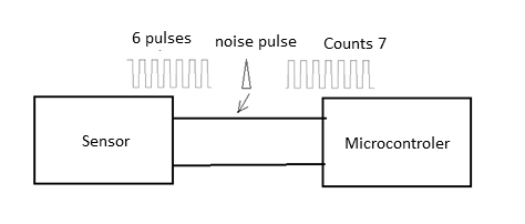
Therefore, when using additional sensors or input circuits such as Shields, extreme caution must be exercised with cables and uncoupling.
If you notice that something is malfunctioning in pulse counting, in sensing its sensor's logical levels, we have the following solutions to try:
a) Shorten cables
A first recommended procedure, when problems with sensor interfacing or Shields cause instability, is to shorten the connection cable. In some cases, the noise level picked up is reduced to the point of eliminating the problem, but if it does not resolve, proceed to the next item.
b) Shield cables
In most cases, the circuits operate in very noisy environments. In demonstrations, we have seen at events, the noise level is high, caused by the power grid, LED (light Emitting Diode) and fluorescent lamps as well as air conditioning equipment and others, to the point of affecting the operation of processed circuits. In this case, we should think about the shield.
But a shield has no effect if the outer cable mesh is not grounded. As shown in Figure 2, the mesh must be grounded (GND or 0 V) ??of the circuit.
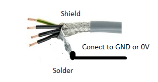
A shield only works if it is grounded according to the Faraday Cage operating principle.
c) Uncouple cables
Many sensor and shield power cables can also cause operating instabilities in microcontroller circuits. A longer + B cable or 5 V power may facilitate noise input or signal feedback when switching occurs.
If there is in your microcontrolled circuit, for example, an Arduino, a long cable that connects to an external source or that feeds a shield or a sensor, that cable can be feedback because it behaves like a resistor.
When the circuit switches and there is a small peak current, the cable acts as a pulse generator circuit and these pulses are carried to neighboring circuits, as shown in Figure 3.
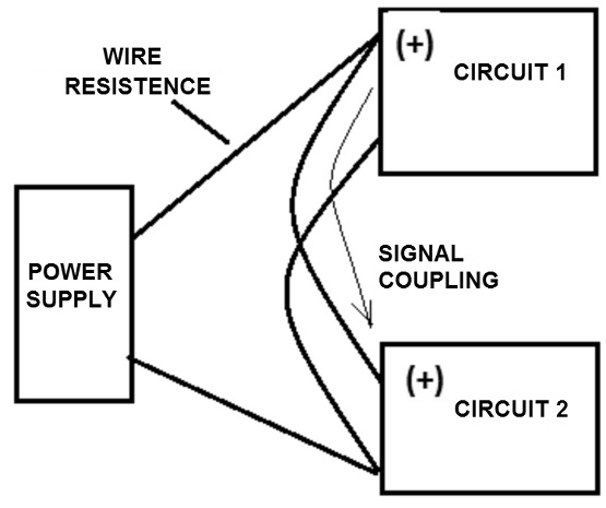
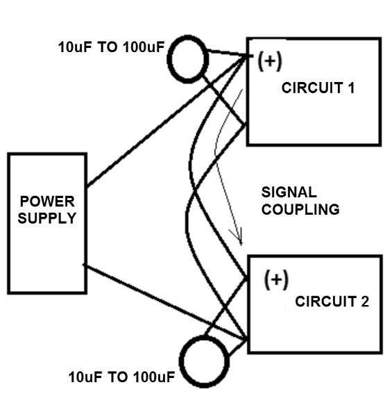
What we do in this case is to connect at the ends of this cable electrolytic capacitors typically from 10 to 47 uF to decouple the signals. These capacitors act as “dampers” preventing voltage fluctuations caused by switching.
The capacitors can be at one or both ends, as shown in Figure 4.
d) Uncouple circuits
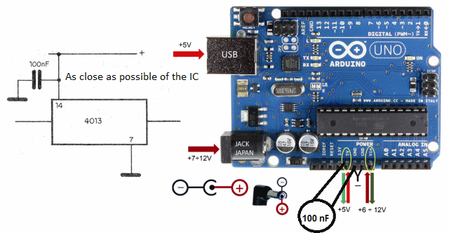
But even on the board itself or on boards which have sensitive integrated circuits, it may be necessary decoupling and this is precisely when working with older integrated circuits that do not provide greater immunity to variations in the supply current.
What we do is to connect the power point of these integrated to capacitors between the power supplies, better than what we show in Figure 4. So, as shown in Figure 5, we typically connect 100 nF ceramic capacitors between the 5 V + Vdc and the GND of the interphase integrated circuit.
e) Shield the Assembly
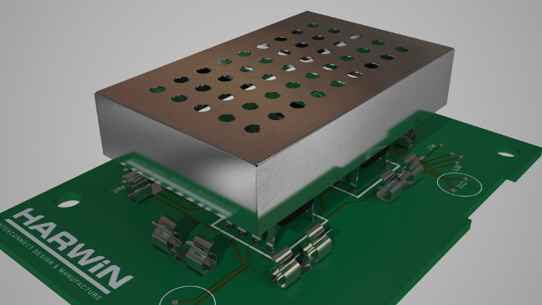
In some cases, the indicated procedures are not sufficient and the solution will be to shield the assembly. We then use the Faraday cage principle. We put the sensitive circuit inside a metal box and connect this box to the source GND or 0V, as shown in Figure 6.
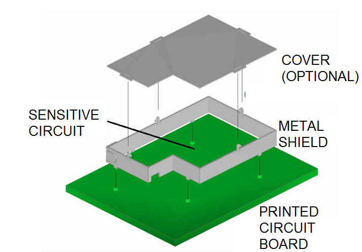
In some cases, simpler shielding for only the sector causing the problem may be enough. Thus, a copper board surrounding the affected circuit point and connected to the GND or 0V circuit can solve the problem, as shown in Figure 7.
We then move on to other older integrated circuit families which can be used with Arduino and other microcontrollers and eventually need the same care we have seen so far in terms of decoupling and instability. For voltage comparators, we can smoothly use the LM339 and its equivalents and one operating that fits most 5V applications is the LM324. (Figure 8)
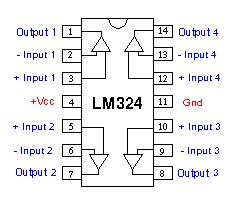
This operating has a bandwidth of 1 MHz and operates with voltages from 3 to 32 V and 100 dB gain. On the website, we have many Shields using this component. For the LM339, whose pinout is shown in Figure 9, the power supply ranges from 2 to 36 V which makes it a component capable of interfacing directly with microcontrollers.
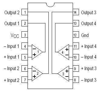
The output supports TTL and CMOS logic.
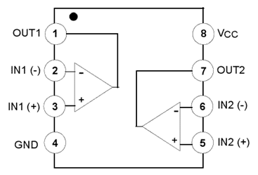
Another comparator compatible with microcontrolled applications is the LM358 which operates on voltages from 3 to 32 V and has the difference from the previous one to have two per enclosure, as shown in Figure 10.
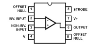
A popular operation, we have explored in hundreds of articles and designs is the CA3140. Being CMOS has huge input impedance and low consumption which makes it ideal for interfacing with microcontrollers. This component operates at voltages from 4 to 36 V.
Other interesting operations for microcontroller applications are the TL071, TL082, LM311. The reader can go to the Mouser website (www.mouser.com) and access the datasheet for many of them, as well as on our website.


