Regulation and Adjustment
Using a transformer, rectifier, and filter as we have seen so far, we already have a continuous voltage that can be used to power certain loads. However, due to the characteristics of the capacitor and the pulsating current itself, the voltage on the load will vary depending on whether it requires more or less current. In other words, the voltage is not stabilized or regulated.
To obtain a constant voltage over a load, a voltage that does not change when the load consumption changes or even when the input voltage of the circuit varies, we need to have a voltage regulator circuit. For the regulation of the supply voltage there are several configurations that can be used.
Some simple based on few components and others sophisticated, based on complex integrated circuits. Let's start with the simplest way, because through it we can understand how everything works.
The simplest way to regulate a source is to take advantage of the electrical properties of zener diodes. The zener diodes, when polarized in the reverse direction, keep the voltage between their terminal’s constant over a wide range of current values, as shown in Figure 1.
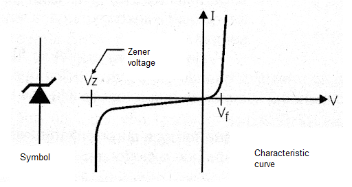
Thus, if we connect a zener diode after the filtering circuit of a source, as shown in Figure 2, the voltage on the zener, which is the voltage on the load connected in parallel with it, remains constant.
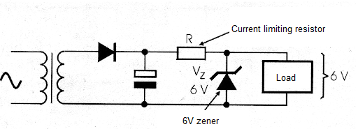
The resistor is calculated so that at the minimum load current there is a maximum current at the zener diode which still makes it maintain the zener voltage between its terminals and below its dissipation capacity.
On the other hand, when the current at the load is maximum, the voltage drop in the resistor must be compatible with the voltage input of the circuit. As zener diodes, in general, are components of small dissipation, this type of regulator is not used much as we have described it.
However, we can take advantage of the properties of the zener diode to design circuits which are more efficient, both in keeping the load voltage and in handling high currents. Thus, there are two possible configurations for voltage regulators used in linear sources: in series and in parallel.
Serial Regulator
The basic idea of a serial regulator is to connect in series to the load supply line a circuit that functions as a variable resistor with reference to a zener diode, as shown in Figure 3.
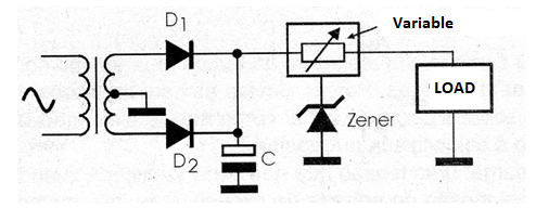
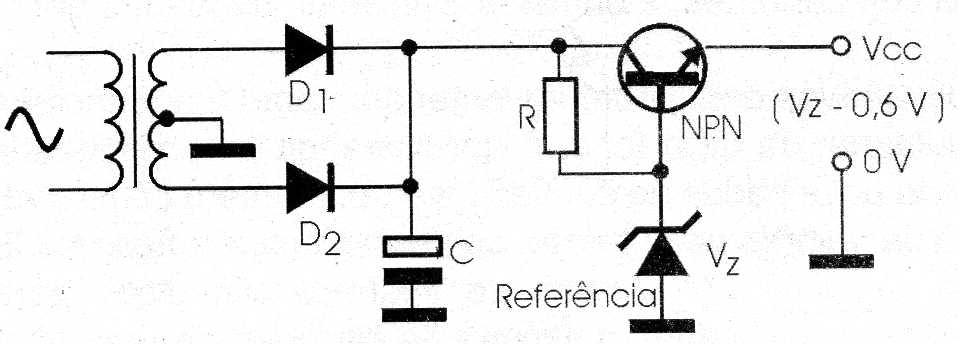
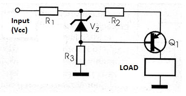
Based on information from the zener diode and the output voltage itself, through a feedback circuit, the regulator changes its resistance in order to keep the voltage at the load constant, regardless of the current it is draining. The simplest configuration for this circuit is that using an NPN transistor, a zener diode and a resistor, as shown in Figure 4.
The zener keeps the voltage at the base of the transistor constant, polarized by the resistor. As for driving, the base voltage of the transistor must be approximately 0.6 V higher than the emitter voltage, with the use of the zener as the reference, we guarantee that the circuit will always behave in order to maintain the emitter voltage 0.6 V below the base voltage, as shown in the same figure.
Thus, using a 12.6 V zener diode, we guarantee that at the transistor emitter, to which the load is connected, the voltage will always be 12 V. Note that, for this circuit, we must consider the voltage drop in the transistor when it drives.
This means that the input voltage of this circuit must be at least 2 V higher than the voltage we want at the output. The resistor, on the other hand, must be calculated so that it supplies the current the transistor needs to saturate and at the same time maintains the voltage the zener diode needs to function.
The advantage of this circuit is that the zener diode has a small current in relation to the current required by the load, as this current is amplified by the transistor. The disadvantage lies in the fact that the transistor behaves like a variable resistor with a high-power dissipation, depending on the current drained by the load.
Even in relatively small sources, the transistors used in this type of circuit must have good heat radiators. In practice, only in the simplest sources is the configuration given as an example used.
More elaborate circuits can be achieved using Darlingtons, and even additional features like short circuit protections, etc. Thus, following this configuration, we have many voltage regulators with three terminals in the form of integrated circuits.
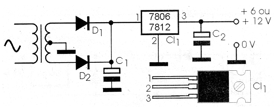
There are basically two types of serial regulators for use in power supplies: fixed and variable. The fixed regulators have an internal zener which already determines the output voltage. Thus, the terminal of this zener is normally connected to earth as in the case of the 6 and 12 V regulators, 7806 and 7812, as shown in Figure 5.
See that these regulators are provided with housings which allow their direct mounting on heat sinks. Minor changes in the output voltage can be achieved with the addition of an additional external diode that will add up to its internal diode voltage, as in the case of Figure 6.
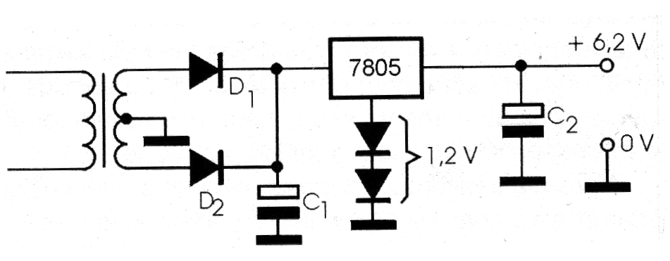
In the indicated configuration, using two common diodes polarized in the direct direction, they will add 1.2 V to the voltage of a 6705 of 5 V outputs, thus obtaining a 6.2 V output. The 78XX series integrated circuits, according to characteristics given later in this book, can control currents up to 1 A in its basic version.
To obtain more current than the circuit can supply, it is normal to use additional transistors in the configurations shown in Figure 7.
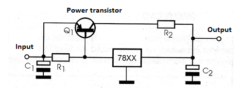
Note that if transistors are connected in parallel, emitter resistors must be aggregated for correct distribution of currents between them. It is also important to note that the regulation does not necessarily have to be done on the positive power line.
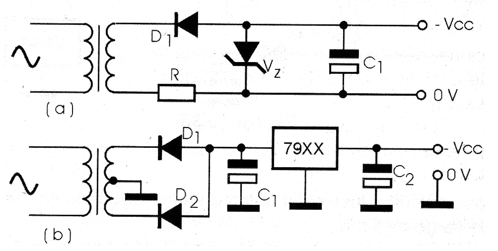
In symmetrical sources, it is common to use positive and negative voltage regulators at the same time. Both the zener diode and the more sophisticated regulating circuits themselves can make negative voltage regulation, as shown in Figure 8.
The integrated circuits of the 79XX series, for example, are negative voltage regulators. It is also important to note there are regulators which have internal zeners of low values, which allows adding an external circuit to adjust the output voltage.
Then, we have the variable regulators (which can be both negative and positive) capable of controlling quite high currents. We cite as an example the LM317 and LM350 regulators which we will deal with in this same book with more details. This category can also include the 723.
Shunt Regulator
A less common way of regulating the voltage of a source is through a shunt regulator, whose basic configuration with a transistor is shown in Figure 9.
This regulator works as a high power zener, deriving the current in the load so that the voltage between its terminals is kept constant. The circuit is calculated in such way that the currents drained by the load and the regulator combined, result in a resistance which, in series with the input R resistance, generates the load supply voltage.
Thus, when the load increases its consumption, the regulator decreases, which causes the sum of the currents to be maintained and thus the voltage in the load. The great disadvantage of this circuit is that the power dissipation is constant, even when the load is at its minimum consumption.
Furthermore, depending on the load current, the regulator can dissipate high powers, thus requiring the use of large sinks and transistors with high current capacity.

