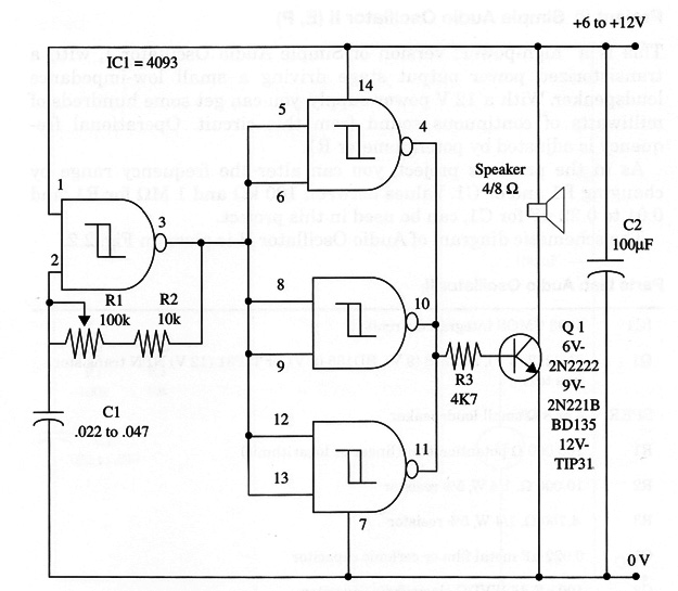
As in project ART115E, you can alter the frequency range by changing R1 and/or Cl. Values between 100 kohm and 1 Mohm for R1, and 0.01 to 0.22 µF for Cl, can be used in this project.
The schematic diagram of Audio Oscillator II is given in Fig. 1.

Transistor Q1 depends on the power supply voltage. In the 9 V and 12 V versions, the transistor must be mounted on a heatsink. You can also use a power FET-any IRF type with drain current rated to 2 A or more.
The circuit can also be used as part of alarms, toys, games, and to teach the reader a great deal about audio oscillators using the 4093.
Current requirements for this circuit depend on the power supply voltage and the Ioudspeaker’s impedance. Typically, they range from 10 to about 500 mA. With power FET and supplies between 12 and 15 V, the circuit can drain up to 2 A.
IC1 - 4093 CMOS integrated circuit
Q1 - 2N2222 (6 V), 2N2218 (9 V), BD135 (9 V), or TIP31 (12 V) NPN transistor (see text)
SPKR - 4 or 8 ohm small loudspeaker
R1 - 100,000 ohm potentiometer (linear or logarithmic)
R2 - 10,000 ohm, 1/4 W, 5% resistor
R3 - 4,700 ohm, 1/4 W, 5% resistor
C1 - 0.022 µF metal film or ceramic capacitor
C2 -100 µF, 16 WVDC electrolytic capacitor


