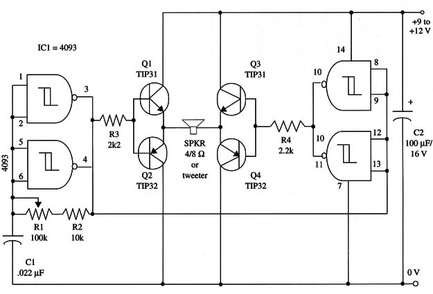
Higher values for C1 will give sound in the audible range, which allows the unit to be used in alarms and other applications. In this case, the tweeter can be replaced by a common loudspeaker.
The circuit drains some hundreds of milliamperes from a 9 V to 12 V power supply. Batteries are recommended for momentary operation only.
The reader can use this device to scare dogs and other animals by installing the unit near waste deposits or other places where unwanted animals can be present.
Ultrasonic operation is achieved with a C1 value between 470 and 2,200 pF.
Audible operation will occur with C1 in the range between 0.01 and 0.022 µF.
A schematic diagram of the powerful ultrasonic generator is shown in Fig. 1.

The transistors must be mounted on heatsinks. All components can be housed in a plastic box. The value of capacitor Cl depends on the frequency range you want to generate.
IC1 - 4093 CMOS integrated circuit
Q1, Q3 - TIP31 NPN silicon power transistor
Q2, Q4 -TIP32 PNP silicon power transistor
SPKR 4/8 ohm tweeter or loudspeaker (see text)
R1 - 100,000 ohm potentiometer
R2 - 10,000 ohm, 1/4 W, 5% resistor
R3, R4 - 2,200 ohm, 1/4 W, 5% resistor
C1 - 1,200 pF (ultrasonic) or 0.022 11F (sonic) metal film or ceramic capacitor
C2 -100 µF, 12 WVDC electrolytic capacitor


