Each of the four characters in our problem consists of a sliding-type potentiometer which can move from one bank of the river to the other. Thus, the player, always taking two at a time or one, can make the crossing taking it/them to either side of the river. If a situation where the wolf eats the goat, or the goat eats the lettuce, the circuit will detect it by triggering an oscillator. (Figure 2). Remember, of course, that wolves are not vegetarians, that is, they do not eat lettuce!

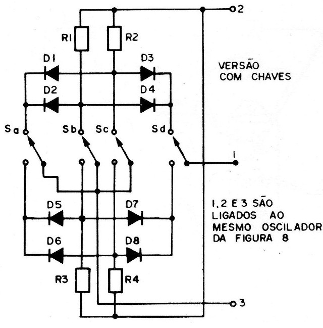
Although the version using slide-type potentiometers is the most interesting due to the realism it can provide, in the absence of this component, reversible switches can be used. To facilitate the readers, we will give the diagrams for the two assemblies.
Likewise, in the end, we will give the solution to the problem, so that the reader who set up the device is spared of an embarrassment in front of their friends!
HOW IT WORKS
We can say that our circuit basically consists of a logic system capable of providing an output when an unwanted situation is established, thereby triggering an oscillating circuit which emits the alarm sound.
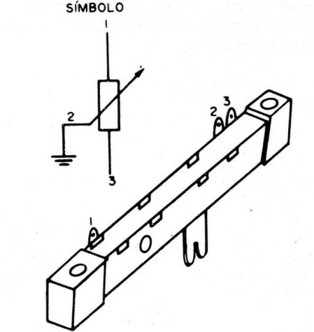
Each potentiometer can be moved up or down, placing its ends in a very low potential, since the cursors are connected to the ground (Figure 3).
Therefore, the diodes connected in such a way to conduct only when undesired situations are reached, can trigger or not the alarm system. Thus, the arrangement of the diodes and the connection of the potentiometers are made in such a way that, there is no signal at the output unless a situation in which one "passenger" can eat the other is reached.
In short, the arrangement of the diodes is done in such a way that we have in the gate of an SCR, that is, at the exit of the circuit, a signal when the goat is alone with the lettuce on a riverbank or when the wolf is alone with the goat on a river bank. The same system prevents an exit, inhibits, when the man is close. This way the alarm will not sound when the man, the goat and the wolf are on the same bank, which is to say that "the man does not let the goat eat the lettuce".
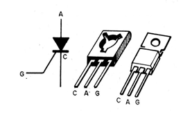
The circuit output is applied directly to the gate of an SCR, which will therefore be triggered when any prohibited situation is reached. As we already know, from other assemblies, an SCR, or Silicon-Controlled Rectifier, consists of a device that conducts the current intensely when a signal is applied to its gate. (Figure 4)
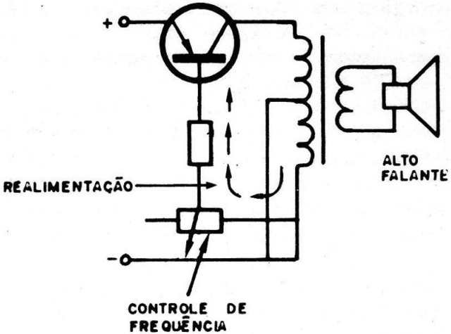
This SCR is connected in series to an oscillating circuit whose function is to produce an alarm signal when the prohibited situation is established. It is a Hartley oscillator, a circuit equipped with a transistor and a transformer with a central socket. Through the transformer derivation, the signal feedback is maintained, which keeps the circuit oscillating (Figure 5).
The operating frequency of this oscillator and, therefore, the timbre of the alarm signal, can be adjusted slightly by the feedback made through the base resistor, which in our project will be of the variable type (trimpot).
The entire circuit will be powered by a continuous voltage of 6 Volts, and at this point an observation must be made regarding the only critical point of its operation:
The SCRs only "turn off" when the voltage between their anode and cathode drops to a low enough value, after an excitation pulse. Thus, in our case, this voltage is obtained by the "inductive" behavior of the oscillator transformer. If the transformer is not of the type recommended in the material list, it may happen that after a player misses the crossing and the alarm is triggered, returning the device to the starting position it does not turn off. In this case, one should try to replace the transformer with a type that leads to the results.
ASSEMBLY AND COMPONENTS
For the assembly of this game, the reader will need the tools that are normally used in electronics work, that is, a small power soldering iron (maximum of 30 Watts), good quality soldering, side cutting pliers, needle-nose pliers and screwdrivers. The tools for creating the box that will house the device must also be considered in this case.
Regarding the components used, we have two observations to make:
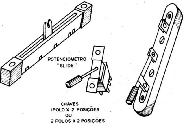
a) The slide pots
These potentiometers, although they can already be found easily in cities with more intense e-commerce, one may not be able to do so in smaller cities, since they are relatively new components. (Figure 6) Thus, if there is difficulty in obtaining it, the reader must choose the circuit which uses reversible keys, as these are more common and can be found much more easily. The circuits for both versions will be given.
b) The oscillator transformer
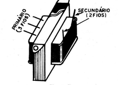
The transformer used in the oscillator circuit is of the miniature type normally found in portable radio output circuits.
These transformers have a primary with central outlet with an impedance between 200 and 1,000 ohms and a secondary of 8 ohms, that is, according to the speaker used. (Figure 7) If the oscillator does not turn off when it returns from an allowed situation, the reader should try to replace one with characteristics that best adapt to the purpose of the project.
Returning to the assembly, start preparing the box to receive the pots or switches. In the case of switches, these can be mounted side by side, as done in the prototype, making a rectangular hole in the 6 x 4 cm appliance panel.
The loudspeaker can be installed internally, if space is available, or externally, with the switch on and off the circuit on the side.
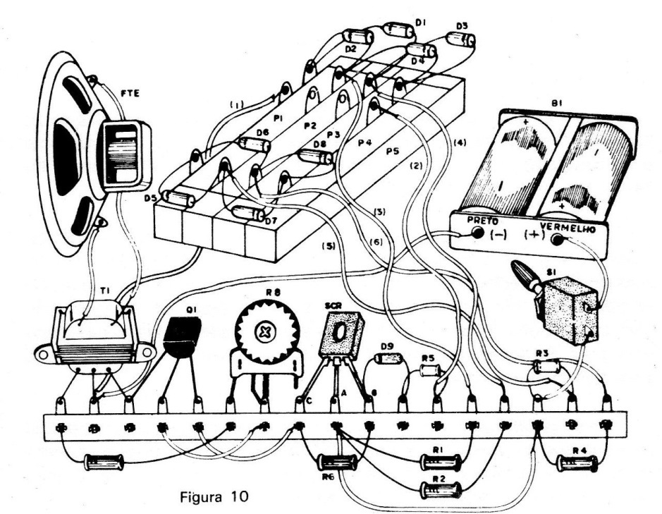
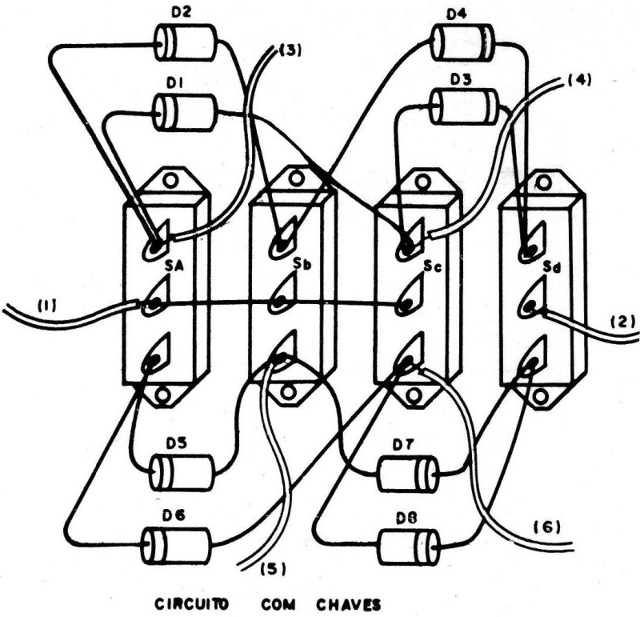
The diodes which form the circuit for detecting the prohibited situation will be soldered directly to the terminals of the potentiometer or switches. For this purpose, follow the circuit for the two versions, given in Figure 8 and Figure 9.

Follow the layout on the terminal strip (plated) in Figure 10 and Figure 11.
The supply will be made by means of 4 small cell batteries that will be installed in an appropriate support placed inside the box. As the consumption of the device is very small, the battery life will be long.
After the connection of the diodes is complete, work on the terminal bridge, welding the SCR first, carefully observing its position (the flat side must be to the right, or the plastic part upwards). Then release the oscillator transistor, also observing its position. If it is of the plastic type, the flat side should face up. If it is of the metallic enclosure type, see the identification of its terminals in Figure 12.
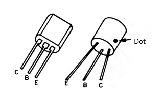
If the transformer is of the type with rigid terminals, they may be welded directly to the bridge keeping this component in position. If the terminals are flexible, proceed with the welding, then fix the component appropriately.
Then weld the trimpot and other components in position, observing their position in the case of the diode.
After the soldering of the components is complete, proceed with the interconnections between them, and between the sliding potentiometers, the battery holder, and the speaker with flexible thin wire. The wires can be compressed which is no problem.
The S1 switch is used to turn the device on and off, being fixed on the side of the box that houses the device.
Complete the assembly by cutting the front panel, drawing a river in it, as suggested in the figure in the introduction, and on the buttons of the sliding pots draw or write the "passenger" they represent.
In the case of mounting with the switches (instead of sliding potentiometers), only the front panel changes, in which case the "passenger" they represent must be indicated in each case.
TESTING AND PLAYING THE GAME
Once the assembly is complete, check all connections, and if everything is in order, turn on the switch that establishes the circuit supply.
Then, put all the switches in the position that corresponds to one side of the river, that is, all up or down (the same being true for the slide pots), and take the switch corresponding to the man to the other side. The oscillator should immediately emit its characteristic sound, that is, a whistle. (Figure 13)
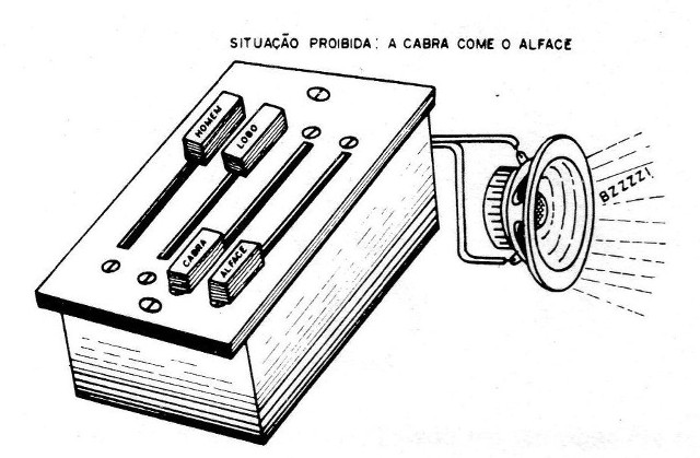
If this does not happen, adjust the trimpot so that the sound is emitted.
If there is no sound emission in any position of the trimpot, check the assembly again, as something is wrong.
Once the adjustment has been achieved, return the key or pot corresponding to the man to the riverbank where all the "passengers" are. The oscillator must stop ringing. If this does not occur, it may be due to the improper characteristics of the transformer, and replacement with an equivalent one should be provided.
If everything is in order, you can be the first to try the crossing "Without letting the alarm go off, that is, without letting one passenger eat the other".
For this, you must push to the opposite bank of the river, only two pots or switches at a time, one of which must be the one corresponding to the man (since only he knows how to row).
On the other side, the man can return alone, or if he wants, with a single passenger.
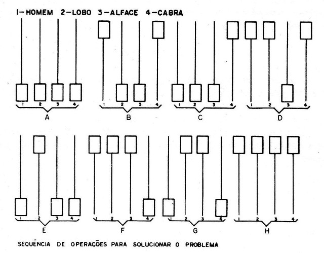
Try the crossing, and if you cannot, see the solution below.
SOLUTION
a) Take the man and the goat to the other side of the river, because with the wolf and lettuce on one side, nothing happens, because the wolf does not eat lettuce!
b) Next, turn the man over.
c) The man then moves to the other bank carrying the lettuce. When he reaches the other bank, nothing happens because the presence of the man prevents the goat from eating the lettuce.
d) On the way back, the man must bring the goat, because if it stays on the other bank, it will eat the lettuce.
e) On the shore here, leave the goat and take the wolf, leaving the wolf on the other shore, returning the man alone. With the wolf and the lettuce standing on the other bank, nothing happens, because as we have seen, the wolf does not eat lettuce.
f) Returning alone, the man can take the goat, completing the transport of the three passengers as was desired. (Figure 14)
R1, R2, R3, R4 - 22 K ohms x 1/4 W - resistor (red, red, orange)
R5 - 10 K ohms x 1/4 W - resistor (brown, black, orange)
R6 - 100 K ohms x 1/4 W - resistor (brown, black, yellow).
R7 - 2.2 K ohms x 1/4 W - resistor (red, red, red).
R8 - 47 K ohms - trimpot
P1, P2, P3, P4 - slide potentiometers of 1M ohms or 500 K ohms. (470k)
D1, D2, D3, D4, D5, D6, D7, D8, D9 - common silicon diodes (1N914 or equivalent).
SCR - TIC1 O6, MCR106, C1O6 - controlled silicon diode for 50 V or more.
Q1 - BC307, BC308, BC309 - transistor. (BC547, 548 or BC549)
T1 - output transformer for transistors (see text).
FTE – 8-ohm speaker.
B1 - 2 small cell batteries connected in series.
S1 - Simple switch.
Miscellaneous: box to house the set, battery holder, terminal bridge, buttons for slide pots, screws, wires, nuts, solder, etc.
COMMENTS
a) In the case of the version with reversible switches, instead of P1, P2, P3 and P4, the following must be purchased:
Sa, Sb, Sc, Sd - reversible switches 2 poles x 2 positions or 1 pole for two positions, lever, knife or slide.
b) At points A and B in the circuit, a buzzer of the type used as a bicycle horn can be connected for 3 volts with the same effects as the oscillator.
c) How about creating a version using a microcontroller like Arduino with sophistications such as the inclusion of point counting by the number of attempts?

