Dozens of sensors can be wired in parallel or series, and each will cause the alarm to operate when activated. Current in the sensors is only few milliamperes, so they can be placed hundreds of feet away from the circuit without risk of problems caused by high cable resistance.
The circuit drives a relay that can be used to control sound sources such as sirens, horns, and so forth.
Power comes from 6 V or 12 V batteries, depending on the relay. Standby current is only 2 mA when the alarm is in the off condition, so it causes a negligible drain on the supply battery.
The sensors can be microswitches or reed types, and the alarm can be made to operate whenever a door or window is opened or when an object moves beyond a preset limit. You can also use pressure-pad switches.
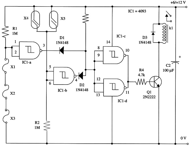
Note that the alarm operates when X1, X2, or X3 is open, or when X4 or X5 are closed, so you can use both normally open or normally closed switches.
A schematic diagram of the General Purpose Remote Alarm is shown in Fig. 1.

A DPDT mini relay rated at 1 A (Radio Shack 275-249) can be used with a 12V power supply and loads up to 1 A. For more powerful loads, you can use a 10 A SPDT mini relay, Radio Shack 275-248.
To reset the alarm you have to close any open sensor (X1, X2, or X3) or open any closed sensor (X4 or X5). Latching alarms are given in other projects Within this book.
IC1 - 4093 CMOS integrated circuit
Q1 - 2N2222 NPN general purpose silicon transistor
D1, D2, D3 - 1N4148 general purpose silicon diodes
K1 - 6 V or 12 V relay (see text)
X1, X2, X3 - Normally closed sensors (see text)
X5, X6 - Normally open sensors (see text)
R1, R2 - 1,000,000 ohm, 1/4 W, 5% resistors
R3 - 100,000 ohm, 1/4 W, 5% resistor
R4 - 4,700 ohm, 1/4 W, 5% resistor
C1 - 100 µF, 16 WVDC electrolytic capacitor


