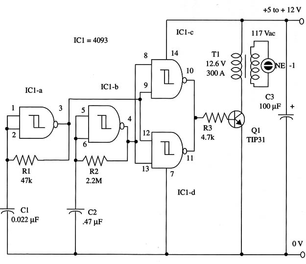
The circuit can be powered from supplies ranging from 5 to 12 V. The duty cycle is 50 percent and, to maintain the lamp “on” during large output pulses, a modulation is applied from IC1-a, which works as a low-frequency oscillator.
If you are supplying the unit from 9 V or greater power supplies, transistor Q1 must be mounted on a heatsink.
Transformer T1 is a small, non-critical power transformer with a 117 Vac primary and a 6 to 12 Vdc secondary. Secondary current can be rated from 100 mA to 300 mA.
Perform experiments with the power transformers you have on hand.
The neon lamp is an NE-2 or NE-2H, and a series resistor is optional.
Depending on the desired light level, you can perform experiments with 1 to 100 k ohm resistors. A schematic diagram of the Neon-Lamp Flasher is shown in Fig. 1.

Components are placed on a solderless board or printed-circuit board except the transformer and neon lamp. Transistor Q1 must be mounted on a small heatsink.
Small, 4 to 15 W fluorescent lamps can be powered from this circuit. Perform some experiments with the ones that no longer function on the ac power line.
IC1 - 4093 CMOS integrated circuit
Q1 - TIP31 NPN Power silicon transistor
T1 - Power-transformer (see text), Radio Shack 27 3-1385, 12.6 V, 300 mA is suitable
NE-1, NE-2, or NE-2H Neon lamp, Radio Shack 272-1101 or 272-1102
R1 - 47,000 ohm, 1/4 W, 5% resistor
R2 - 2,200,000 ohm, 1/4 W, 5% resistor
R3 - 4,700 ohm, 1/4 W, 5% resistor
C1 - 0.22 µF ceramic or metal film capacitor
C2 - 0.47 µF ceramic or metal film capacitor
C3 -100 µF, 16 WVDC electrolytic capacitor


