There are millions of electronic equipment such as televisions and radios with more than ten years of use still in operation in our country. A survey reveals that we have a vast amount of televisions in use in our northeast even from the time of the tubes and a good part of them is not even in colour!
One of the components that these devices use and that gives technicians a good amount of headache is the high voltage electrolytic capacitor, which can be found in reasonable quantities in power supplies and other sections of circuits.
These capacitors lose their capacitance with time, even when they are not used. If they are out of use for a long time, they lose their characteristics and present low resistances (leakage) and a loss of capacitance.
It would be interesting for the repair technician to use the components from repair parts or even recover the faulty ones, as high-voltage capacitors cannot always be easily found and are expensive.
Many technicians would be happy if it were possible to recover electrolytic capacitors without capacitance or leakage by some process.
In this article, we will show that this is possible and in a straightforward way. Of course, not all electrolytic capacitors can be recovered, but the technician's "profit" can pay off if a part of them can.
To understand how recovery is possible, it will be interesting to analyze the functioning of electrolytic capacitors as a starting point.
ELECTROLYTIC CAPACITORS
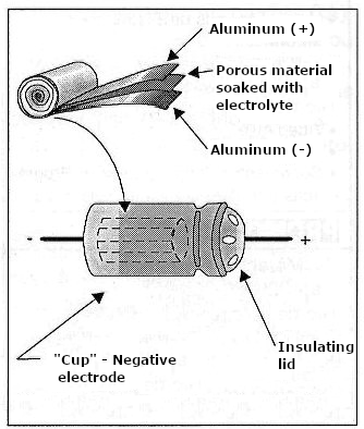
Electrolytic capacitors have a chemical working principle. As shown in Figure 1, we have rolled aluminium sheets soaked in a chemical called electrolyte.

This electrolyte chemically reacts with aluminium forming a thin insulating oxide film that works as a dielectric. This film's minimal thickness and good dielectric constant make it possible to obtain very high capacitances for this type of component.
However, it happens that, in operation, the presence of voltage in the armatures constantly regenerates this reaction to maintain the layer of insulating material and, therefore, the capacitance of the component.
If we reverse the capacitor's polarity, the electric current that passes through the insulating layer destroys it. That's the reason why electrolytic capacitors cannot be used inverted. A powerful electric current in the reverse direction can generate enough heat to cause the electrolyte to boil, which can cause the capacitor to explode.
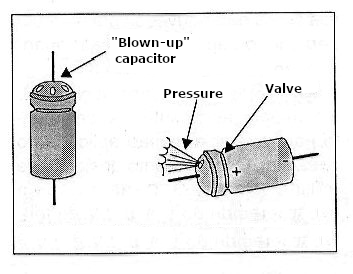
In old capacitors, this explosion can have dangerous effects because there is no pressure relief valve. In the most modern ones, a small valve allows the "pressure" to escape if something abnormal happens to the component, as shown in Figure 2.

If the capacitor remains unused for a long time, the insulating layer will change its characteristics, with its thickness becoming irregular and current leakage points appearing. That means that the capacitor loses its capacitance or even starts to leak if it is not used for a long time.
It can be recovered if the insulator has relatively small or non-compromising leakages or a considerable reduction in capacitance.
All you need to do is apply a voltage for a specific time in a controlled manner to the armatures for the insulating material layer to recompose, allowing the component to be used again.
Note, however, that this voltage must be applied in a controlled manner so that the component is not destroyed. If the component leaks excessively and we apply a high recovery voltage, the current generates heat, and it can explode.
Restoring
A typical restoration device allows you to check the leakage of an old capacitor or even if it is short-circuited. If the leaks are not excessive or short-circuited, we can apply a recovery voltage under a controlled current regimen and restore the component.
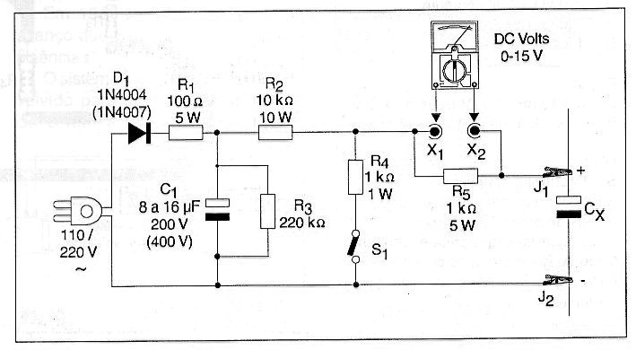
Therefore, a typical circuit consists of a simple transformerless high voltage source with current limiting resistors and an output point for measuring current using the multimeter. Capacitors from 1 to 500 uF for voltages above 200V, if your network is 110V, or above 400V if yours is 220V, can be recovered.
The recovery time is highly dependent on the state of the capacitor. If a capacitor is very bad, its recovery may require up to 24 hours of voltage application. Above that, it will be convenient to throw the component away.
The resistor R5 in parallel with the multimeter allows you to use the 0-15 or 0-30 V DC scale as the current scale. With a 1 k ohm resistor, applying Ohm's Law, we verify that each volt corresponds to a current of 1 mA.
As the average leakage of a capacitor is around 1 mA for every 10 uF, it can be seen that we can work with capacitors from 1 to 300 uF and, if the leakage is smaller, with capacitors of even higher values.
Assembling a restorer
In Figure 3, we have the complete diagram of the restorer.
Note, however, that using non-critical components of considerable size that can even be fixed in a chassis allows the assembly to be made on terminal bridges. The values of the components in parentheses correspond to the 220 Volt network.
The resistors are wired and should heat up slightly during operation.
HOW TO USE
Initially, place the suspected or intended-to-restore capacitor between the clips J1 and J2 observing its polarity. Connect a multimeter at the X1 and X2 on a voltage scale from 0 to 15 or 0 to 30 V or a little higher if your multimeter does not have such a configuration.
By connecting the device to the power grid, we can observe the following:
a) The multimeter needle goes to the end of the scale, indicating the beginning of the capacitor charge and depending on its value, it slowly returns to low values, stabilizing a voltage that depends on the capacitor value.
For every 10 uF, we should have a 1 Volt or less voltage if the capacitor is good. If the voltage stays at the high values or takes much longer than expected to return to the low values, the capacitor could be faulty.
b) If the capacitor is faulty, if the indicated voltage remains at high values for its capacitance or even shows short-circuit signals, we must start the recovery procedures.
Initially, we left the device with the capacitor connected for about 2 hours.
Suppose the capacitor does not show recovery signals with the current dropping to the expected values according to its nominal value, and it shows signs of heating. In that case, we turn off the device and wait for the capacitor to cool down.
We then connect the same capacitor and try the same procedure again for another 2 or 3 hours.
Suppose after that the current shows signs of falling. In that case, this means that we can continue with the procedure, repeating the application of a voltage in cycles of 2 or 3 hours until it drops to satisfactory values.
If with new cycles, there are no signs of recovery, the capacitor must be discarded.
We may close and open switch S1 a few times during the procedure to change the voltage applied to the capacitor. Closing this switch also allows working with capacitors from 50V to 100V of isolation voltage.


